Fuel Polishing? Need Some Insight

The friendliest place on the web for anyone who enjoys boating.
If you have answers, please help by responding to the unanswered posts.

raymond.goff

Veteran Member
Joined
Nov 12, 2015
Messages
66
Location
USA
Vessel Name
Liberty 2
Vessel Make
DeFever 43
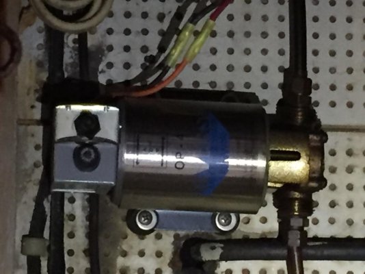
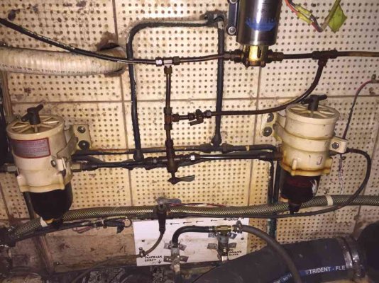
Now that it's warming up, I am starting to crawl through my new to me trawler a bit more. I crawled to the back of the engine room, to look at my filters, and found a device I was not familiar.

I believe it's a fuel polishing system, but I'm not sure which way to turn the handles and how do use?

Since I did not get this from the previous owner, but rather a marina that was in the process of restoring, I have no one to ask how the fuel set up works. In the current configuration the engine runs.
ImageUploadedByTrawler Forum1457900346.439357.jpg


Sent from my iPad using Trawler Forum

Raymond Goff
1978 Marine Trader 34

Our Trawler – m/v Liberty – Travels of a 1978 Marine Trader 34 DC
 
I suggest you make a schematic diagram showing all the valves between the tank and the engine. That should help you figure out how to set to run just through the filters. One word of caution -- some engines can be damaged if the return line is closed.
 
That's pretty convoluted. Clearly the system has been added to a couple of times or more. This is evident between component choices, flare and compression tubing fittings. Looks like a couple fittings may be weeping (leaking) slightly. The other possibility is that the pump may be there to prime the Racors after a filter change. As already mentioned, post a drawing of everything and where the tubing goes so that we're not guessing...as much.

Ted
 
JC! Just like some people should not be allowed to breed, some people should not be allowed to work on their own boats. You have my sympathy.

Do you have two or one engine? Looks more like a priming system to me. But could do both prime and polish. As noted by others, follow and graph out the lines and valves.
 
What's that mess labled "to propeller shaft" and "to packing(?) gland" all about?

Water coming off the engine?
 
What's that mess labled "to propeller shaft" and "to packing(?) gland" all about?


Water coming off the engine?


Might come from the sea water circuit to serve bearing and gland.


best regards / med venlig hilsen
wadden
 
All:

1. The "prop" and "packing" are the water feeds off engine.
2. I neglected to look at the lines back to the tanks, but based on the diagram I just did below, I don't see a return line (which is needed for polishing - right?). I think then this must be for priming...definitely seems weird.
3. Based on the diagram, I think its setup to pull from one tank at a time (right now port tank).
4. Not sure in this setup how the fuel would cycle thru. Pump just for transfer of fuel?

Fuel Diagram.jpg
 
Last edited:
Wow! If your diagram is correct, that was plumbed backwards. Pump is supposed to be pulling vacuum through the racors not positive pressure. Definitely wouldn't use it for polishing as it's currently plumbed. Can you determine directional flow of the pump? Any check valves in the system? Teeing the fuel line to the engine and generator like that, is really a bad idea.


JC! Just like some people should not be allowed to breed, some people should not be allowed to work on their own boats. You have my sympathy.

Mine Too!

Ted
 
It seems to me, based on the picture of the pump, it is bi-directional based on switch position.


IMG_2652.jpg
 
It seems to me, based on the picture of the pump, it is bi-directional based on switch position.
If it's bi-directional, then it's probably used to transfer fuel from one tank to the other in addition to filter priming.

Until you do some replumbing, I wouldn't run the generator and engine at the same time, at least not in critical navigation areas. Generator should have a separator of it's own, not shared. In a better design, the generator draws fuel from one tank through a dedicated draw tube.

You don't need a complicated fuel system; there are some serious design flaws that generate unnecessary failure points in the current system. Drawing fuel from a tank, through a separator, and to the engine should be done as simplistically as possible. Yes, you want to be able to draw from either tank. Being able to switch between 2 separator is nice. All this needs to be accomplished with the least number of valves, fittings, and tubing as possible.

Ted
 
Although I am sure there is an exception somewhere, as a practical matter all diesels over 30 hp return fuel.
 
As drawn.
The pump is a transfer pump, transfer between the two tanks is it's only function.
Looks like normal operation is with fuel in both tanks and levels equal, in this case valve 1 will be normally open. If you want or need to run on one tank only then it can only be the starboard tank, in this case valve 1 will be kept closed.
What is the relative elevation of the fuel tanks and valve 1? if the valve is higher than the fuel level then that's probably / possibly the reason for the transfer pump?? a standard method is to have the cross over line lower than the tanks so that the tanks keep themselves equalised. If they can't do this (due to piping elevation) then periodically you will have to do it with the transfer pump.
The filters are meant to be one in use and one clean filled & ready to go. Valves 2 & 3 perform the selection of "in use" and "stand by" filter. Obviously it is important they are both selecting the same unit !!
Personally I don't think it is a big deal that the generator and main engine is drawing through the filter simultaneously, obviously it would be better if each had their own filter/separator but I believe your question was more about how to operate what you have ?? refining the installation with another filter is something to put on a jobs list.
I don't see much point in valves 4 & 5 they are both normally open, I would fasten them in the open position with locking wire or tyrap etc. For the future I would retain them, they aren't doing any harm and might come in useful when you are changing the engine mounted fuel filter.
hope this helps you
 
"Although I am sure there is an exception somewhere, as a practical matter all diesels over 30 hp return fuel."

Many will only return the internal leakage inside the injection pump.
 
"Although I am sure there is an exception somewhere, as a practical matter all diesels over 30 hp return fuel."

Many will only return the internal leakage inside the injection pump.

When I took pictures the other day, I did not trace past engine. I will do that if I make it over to the boat today. Make sure diagram is right.

It does seem now, based on Stone Beach feedback, that my Racor setup is a Primary and Backup. I originally thought is was one per inbound feed. But then I released what I thought were feed lines were actually the outbound that bent around and connected to the engine feed.
 
I couldn' t get a drop of fuel to return from my Lehmans at 1000 rpm ...after 10 minutes I gave up.

My purpose for doing so was how to run return lines.

I was going from stories about the Bob Smith engine class where they run a Lehman in the parking lot and when someone asks about a return line, they are told it's not needed (in this situation). Must be so little fuel returned cleanup is easier than a return line.

The diagram shows a system not too different than mine. I suspect the pump is for transfer, priming only.....not polishing. To work as I am guessing, that pump has to be a pump where there is no leakage past the impeller or I scanned the system too fast.
 
Last edited:
It seems that Bob Smith doesn't do those anymore. Anyone aware of diesel sessions elsewhere? It looks some there may be some at the trawlerfests. Are those worth anything.
 

Latest posts

Back
Top Bottom