The Fuel System Upgrade Project

The friendliest place on the web for anyone who enjoys boating.
If you have answers, please help by responding to the unanswered posts.
Loctite 30561 is what I suggest. Grainger sells it. It is a liquid Teflon, great stuff. NPT stands Pipe Taper. The deeper the threads the tighter it gets. Brush the Teflon heavy on the threads the tighten snug, most folks tend to overtighten.
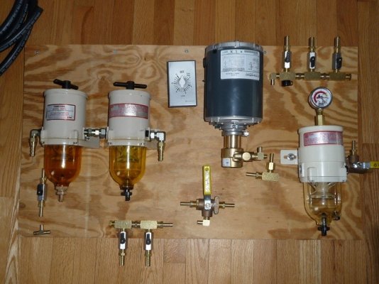
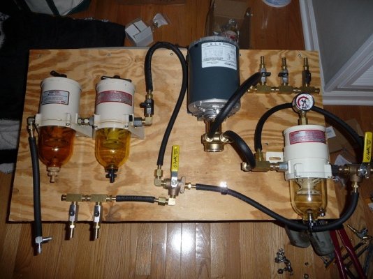
Tom- with all due respect- let's all contribute and begin to neaten up your mock up before you commit to it.
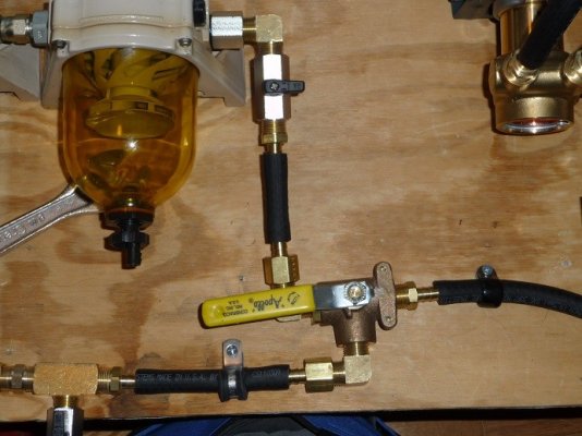
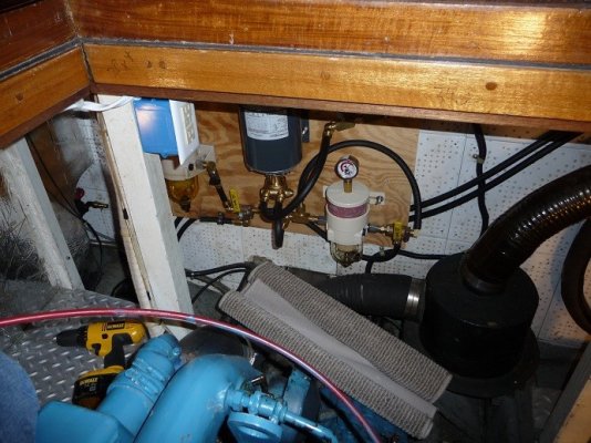
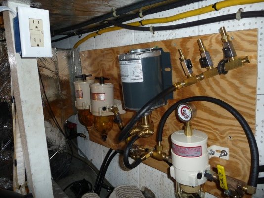
Starting with your original twin Racor housings. Right side. You loop up then down to a three way valve as I recall. Why not come out of the Racor facing down and go straight to the valve?
 
Thanks... At the time, doing it that way got in the way of operation of the valve handle. But also at the time, the exit of the 3-way went a different way. Here is the fix:
 

Attachments

  • mockup4.jpg
    mockup4.jpg
    102.4 KB · Views: 59
MUCH better!
Now the pump. The fittings exit facing out. Not cool. Can the pump be rotated on the motor? We need to figure out a way to have the fittings exit to the right.
 
Here is a suggestion. Where the ball valves are with the long handles, make sure there is a provision to be able to lock the handle if it is in the vertical position while underway.
You can velcro, or tiewrap to a hose or add an eye or whatever in the appropriate place.

I say this because I have had a handle vibrate closed on me once. It wasn't pretty. I won't go into the details here.


-- Edited by jleonard on Friday 11th of February 2011 09:23:39 AM
 
Forkliftt wrote:

MUCH better!
Now the pump. The fittings exit facing out. Not cool. Can the pump be rotated on the motor? We need to figure out a way to have the fittings exit to the right.
Yes, the pump head can be rotated 360 degrees.* By the way, you can get small thumb handles for any ball valve that are not a lever type and take up a lot less room.

*


-- Edited by Delfin on Friday 11th of February 2011 09:30:05 AM
 
Delfin,
That will help a lot. It looks to me that if Tom turns the pump to the right it may hit on the side of the pump. If that is the case he may want to consider a double layer of Starboard for the pump motor mounting to space it out. There may me a lot better ideas too.
 
Thanks guys... Not much chance of rotating the pump right now. Space restrictive. In fact, it WAS like that originally and I had to change it to get it to fit. I'm curious why it's not cool to face it out? There little to no chance of it being hit.
 
Tom,
I guess what I'm trying to say-
Is that you have taken the time to mock this up, buy the best components and ask advice on the board so that your project turns out as well as possible.
When I take on a new to me project I try to locate an example of how it is done by a professional. Then I hope to understand why he/ she does it that way. Chances are they have either learned from someone already skilled at their craft or have learned from trial and error, correcting their mistakes along the way. I have never seen a fuel pump mounted on a board with a loop coming out. I could be wrong and this is the way a professional would mount it but I don't think so.
I'm pretty certain when you mount the upgraded system in you will want it to look as though a professional installed it.
When you say "space restrictive" do you mean you couldn't bend the hose enough to run up to the manifold?
 
There are a couple of bends that get awkward with the pump exiting to the right. The exit of the filter to the input of the pump is the primary one. With the Tee on the pump's exit makes for a lot of distance. Putting a right angle on either or both would mean a large loop of hose to connect the two points. IMHO, that would look worse. I thought about making a solid connection between the pump and filter, but thought that vibrations from the pump onto the filter could lead to issues and trying to get the pump and filter to the exact same height would be maddening. So it needed to be isolated.

Then, on the output of the pump to the output manifold, if I leave the straight barb there will again be a large loop from one to the other. Put a right angle on it facing up and there is not really enough clearance to get around the pump housing.

This just seemed like the most logical solution.

Tom-
 
Tom,
I see what you mean about a solid connection between the pump and new filter creating problems. Where does the other hose go to that "T's" into the fitting on the new filter?
 
If you mean the polishing filter (the one on the right), it's a bypass line for fuel transfer without filtration. Not sure WHY I have that, but I saw another rig that had it, so, like you, I figured it was common in pro setups. Think I should nix it?
 
I'm not sure what it does- I'm new to this too. Is your polishing filter on the suction side or pressure side of the pump? Maybe somebody in the group can explain what the by-pass hose does.
Now- what if you moved your polishing filter slightly left, added a 90 degree elbow facing down out of the pump- then faced the barb fitting at the "t" straight up. If those two fittings were aligned you could complete the connection with one short piece of hose. Would that work?
Also- the barbed fittings you have- do they require a clamp? They are not what I know as "push-on" fittings.
 
Forkliftt wrote:Now- what if you moved your polishing filter slightly left, added a 90 degree elbow facing down out of the pump- then faced the barb fitting at the "t" straight up. If those two fittings were aligned you could complete the connection with one short piece of hose. Would that work?
It really wouldn't solve much. Still have the problem of the pump output not clearing the motor easily.

Forkliftt wrote:Also- the barbed fittings you have- do they require a clamp? They are not what I know as "push-on" fittings.
All are clamp-on, but one (output of the second of the multi-stage Raycor on the far left, but the hydraulics guy swore it can be clamped too. I am going to try and double-clamp them all.

Repost of pics for reference:
 

Attachments

  • mockup1.jpg
    mockup1.jpg
    112.2 KB · Views: 82
  • mockup2.jpg
    mockup2.jpg
    121 KB · Views: 79
Tom,
Is there a way to come straight out of the pump output, maybe 4-5" then a 90 straight up? Might even use a section of hose for this.
 
Tom,

Bite your tongue!
smile.gif
Permatex indeed. Use the Loctite. My wife works there and I need her to keep me and the boat in the manner to which I ave become accustomed. Permatex used to be a part of Loctite but was sold off.

Only kidding, Permatex is a good product.

Rob
37' Sedan
 
Tom, I don't know what the additional line just downstream from the filter and upstream from the motor would be used for.* I would suggest you deep six that.* Also, please remember that the Procon pump will put out 250 psi.* That was why I suggested A-1 wire braid hose with JIC to NPT fittings.* Lesser hose will work as long as you always remember to open a valve so the fuel has someplace to go...

Permatex did not work for me, but my mistake was using stainless pipe fittings, and I am sure you will have better luck with the brass fittings you purchased.

p.s., now that I look at the picture again, I'm not sure what the extra line and 3 way valve upstream of the filter will do either...

-- Edited by Delfin on Saturday 12th of February 2011 07:59:26 PM
 
Take a look at the new design in the new thread. To finish up this thread, I am posting a few pictures of the old rig set temporarily in place in the bilge.

I can't thank you guys enough for all your help so far. It's been nothing short of amazing!

Tom-

1) The new spin-on CAV filter modification.
2) Looking in the engine room at the rig.
3) The rig closer view
 

Attachments

  • spinon.jpg
    spinon.jpg
    112.1 KB · Views: 65
  • oldinstall1.jpg
    oldinstall1.jpg
    137.6 KB · Views: 79
  • oldinstall2.jpg
    oldinstall2.jpg
    132.7 KB · Views: 78
Back
Top Bottom