How can I damage my alternators?

The friendliest place on the web for anyone who enjoys boating.
If you have answers, please help by responding to the unanswered posts.
Joined
Feb 24, 2008
Messages
681
Location
St. Lucia, West Indies
Vessel Name
"Dragon Lady"
Vessel Make
DeFever 41
I understand that an alternator will be damaged (diodes?) if it is disconnected while the engine is running. Is the damage done by disconnecting the field wire or the heavy charge wire?
 
Heavy charge wire. You can disconnect the field and it just quits making output, won't harm anything.
 
"Is the damage done by disconnecting the field wire or the heavy charge wire? "

THE output "heavy charge wire" or simply shutting off a dumb rotary switch causes the damage.

Turning off the field current is fine , then you could disconnect the battery wire.

A better grade of rotary switch will have field disconnects built in.

They DO have to be wired in , just having them on the switch does nothing.

Internally these are "break before break " switches.

The field is cut first then the battery is cut.

This is a simple cheap setup that should be on every boat with a rotary switch.
 
The switches that FF describes above have an automatic field disconnect feature which has a parallel field switch that turns off the alternator before the switch disconnects power.


But much more common are one, two, all, off switches that make before break. That means that when you switch from one to two or from two to all, the switch makes contact with the new position first before it breaks contact with the old one. This assures that there is always a load connected, presuming that a load is connected to 1 and 2.


But there is no protection with these switches if you switch to off. It will blow the diodes then.


David
 
Thanks everyone - exactly what I needed to know.

David: master switches like you describe make a lot of sense. I will have to check the specs on mine
 
I understand that an alternator will be damaged (diodes?) if it is disconnected while the engine is running. Is the damage done by disconnecting the field wire or the heavy charge wire?

Charge wire as has been mentioned before. I recently changed how my own boat was wired. Keep in mind that I have a small single diesel and a single battery bank. As is typical from the factory, my alternator was wired to the Common post of a 1/2/Both/off switch (make before break type). The problem of course is that if someone were to inadvertently pass through the off position while the engine was running, it could damage the alternator.

I changed this so that the alternator output goes directly to the battery bank, bypassing the 1/2/Both/Off switch. I made some other changes as well, but now the alternator is always charging the batteries when the engine is running. This not only eliminates the concern of damaging the alternator but reduces the number of electrical connections between the alternator and the batteries. FWIW
 
Add an $18 buck RV solenoid on the house side to charge and you will have a seamless charge setup that requires Nothing to have the house charge with the engine on , automatically.

KISS
 
Dave: That is the setup I have - except that the start and house batt are fed via a battery isolator. Fairly safe providing the isolator itself doesn't malfunction.


Fred: I like KISS. Can you please elaborate a bit on your suggestion.
 
Many boats I see rewired, some from factory, have the alternator charge wire led to the positive post on the starter.
 
Many boats I see rewired, some from factory, have the alternator charge wire led to the positive post on the starter.

I have seen this on a lot of sailboats. It has the same effect of wiring the alternator to the common post on a 1/2/Both/Off switch. It is easy to do as the alternator and starter are typically very close to each other.

My plan was to add a dedicated start battery for the engine. I was going to use an echo charger to charge the start battery as both my charger and my alternator are wired directly to the positive post on the house bank. Very simple system.
 
THE output "heavy charge wire" or simply shutting off a dumb rotary switch causes the damage.
Turning off the field current is fine , then you could disconnect the battery wire.
A better grade of rotary switch will have field disconnects built in.
They DO have to be wired in , just having them on the switch does nothing.
Internally these are "break before break " switches.
 
Shoalwaters,
If you have discharged or dead batts recharging w an alternator may overwork it and cause damage. Motorcycles are prone to that especially. Better to charge w charger and then use your boat batt.
 
Shoalwaters,
If you have discharged or dead batts recharging w an alternator may overwork it and cause damage. Motorcycles are prone to that especially. Better to charge w charger and then use your boat batt.

Eric: Your alternator should be fine with a 3 stage external voltage regulator with a battery temperature sensor. That's a pretty standard set up these days. With the exception of one stator, our alternator failures have all been bearings. When we replace the bearings, I do the brushes at the same time.
 
Last edited:
" our alternator failures have all been bearings"

Loose belt or fan used with wrong direction fins might be cause.

Overheating the alt can cause the lubricant to depart....
 
" our alternator failures have all been bearings"

Loose belt or fan used with wrong direction fins might be cause.

Overheating the alt can cause the lubricant to depart....

FF...
You caught my attention... trying to understand your point #1...seems counter intuitive so trying to understand the rationale

loose belt = bearing failure?

I have been under the (incorrect?) impression that loose belt would affect output but belt too tight would relate to bearing failure?

Wouldn't a loose belt = slippage = lower output and LESS heat than if at full output?
 
AS a loose belt slips, the FRICTION of the belt sliding past the pulley heats it to a grand temperature.

Enough to melt the grease in the end bearing.

Try looking with an IR gun.
 
AS a loose belt slips, the FRICTION of the belt sliding past the pulley heats it to a grand temperature.
.

FF

Duh... I forgot about friction.
Like gravity we sometimes overlook the obvious

Thanks
 
Chuckle

I understand that an alternator will be damaged (diodes?) if it is disconnected while the engine is running. Is the damage done by disconnecting the field wire or the heavy charge wire?

The title of your post gave me a chuckle. My first thought was "why would you want to?" Of course I understood what you really wanted to know. Sorry but couldn't resist. :rofl:
 
I ran the charge wire directly to the battery post of the on-off-1+2 battery switch, with an 80 amp red blue sea fuse holder inline. At least that way moving switches wont ever inadvertently disconnect the alternator.
So with 2 engines and 2 banks and 2 switches, each alternator charges it's own bank. And I could move switches to combine them etc...
One bank is for starting, one bank for house.

It works for me so far.
Only negative might be if all switches are off, the charge wire is still hot. But not been a problem. Say you worked on engine and somehow short the charge wire, it would spark and blow the fuse. I almost never turn off those big switches.
 
Last edited:
FF, in my experience it makes no difference which way the fan turns. Its still centrifugal. Probly better if it goes the correct direction but I've not seen it make a diff.
 
" with an 80 amp red blue sea fuse holder inline."

So if the fuse goes , so does the alt?
 
" with an 80 amp red blue sea fuse holder inline."

So if the fuse goes , so does the alt?

Fuses only blow at 125% of their power rating. I have read an alternator can not put out more than its rating without self destructing, so it might burn itself out before the fuse blows. The fuse is just in case the wire shorts, then battery amps would blow the fuse.

Don't know if the fuse goes , so does the alt, the alternators are 78 amp 12SI Delco one wire no external regulator. Since there is no separate wire sensing regulator to keep the field on, if the fuse blows all power is immediately cut to alternator.


I wired mine up this way since it keeps me ar anyone else from moving switches if engine is running and possibly killing the alternator.

I looked at circuit breakers for doing this, but already had one freebie Blue Sea fuse holder, so went with fuses, Just had to buy one fuse holder. You can buy 100 amp fuses for that fuse holder.
 
Last edited:
the alternators are 78 amp 12SI Delco one wire no external regulator.

These are great , when used as created , to refill a start batt , and provide DC power to accessories, underway .

IF you want to charge house batts in a far shorter time , you will need to replace the internal Vregulator and wire in a 3 or 4 stage marine V regulator.

"Fuses only blow at 125% of their power rating.,"

That really depends on the fuse selected , some are instant at the rating , others are "slow blow".

A 200A fuse would give the same protection from a massive short , .

Yes it would. Mine are slow blow Maxi fuses from what I remember, like this
https://www.bluesea.com/products/category/15/51/Fuses/MAXI_Fuses
.
Even at 2 times their rating, 10 seconds to blow.
Maxi_Fuse_Blow_Delay.png

The wire to the batteries is gauge 4. This helps keep the voltage higher. with an external regulator, voltage sensing is at the battery or buss which is good. With a one wire alternator, voltage sensing is at the alternator. When running for me it charges at about 14.6 vdc

I also have an Onan generator and a Raritan charger-converter. I don't have a lot of high power DC stuff. The Lectrasan is the biggest temporary draw. My electric horizontal windlass is AC powered. Inside is a Black and Decker 48vdc motor. AC is converted by a full wave bridge rectifier to DC. It has lots of gears inside, pulls about a foot per second and nothing stops it. I got it real cheap used, don't even know who made it. But I have seen this similar style on some older power boats. It is like a square white box with a single rope pulley and an on-off switch.

The big advantage of AC power is I can run a 16 gauge wire to the windlass. And for AC backup, I have a 3000 watt MSW inverter. Even so, my family mostly hauls in the anchor by hand.
 
Last edited:
Fuses only blow at 125% of their power rating. I have read an alternator can not put out more than its rating without self destructing, so it might burn itself out before the fuse blows. The fuse is just in case the wire shorts, then battery amps would blow the fuse.

Don't know if the fuse goes , so does the alt, the alternators are 78 amp 12SI Delco one wire no external regulator. Since there is no separate wire sensing regulator to keep the field on, if the fuse blows all power is immediately cut to alternator.


I wired mine up this way since it keeps me ar anyone else from moving switches if engine is running and possibly killing the alternator.

I looked at circuit breakers for doing this, but already had one freebie Blue Sea fuse holder, so went with fuses, Just had to buy one fuse holder. You can buy 100 amp fuses for that fuse holder.

Alternator fuses should ideally be sized at 125-150% of the Max alt output rating. Balmar and others recommend 150%. The reason for this is that you don't really want to run an over current protection device at any more than about 80% of its rating, preferably less. Running a fuse at close to its rating also means more voltage drop across the fuse.

The fuse also goes at the battery end of the circuit not the alternator end. This is because the alt is a current limited device but a good sized bank can throw 15,000-20,000A into a dead short.

If a fuse trips in an alt circuit, or a switch is flipped resulting in an open circuit event, an extremely fast voltage transient occurs, faster than the regulator can react to, and it very often blows some or all of the alternators diodes.

The fuse is not really there to protect the alt it is there to protect the wire. However by sizing it too small it can eventually nuisance trip and potentially destroy the alt. When a fuse is constantly run at close to its rating it can eventually develop edge burn, a blackening of the edges of the thermal wire, the longer it goes on the higher the likelyhood it can nuisance trip.

Also many alternators, due to slight variances in manufacturing, can supply as much as 3-7% more than their rating upon cold start for short durations.
 
I'm personally not a fan of fuses on the alternator charging cable. Too many chances of erroneous disconnection of the alt charge that would cause damage to the alternator diode. As it was explained to me, the over-current situation would be controlled by alt circuitry. I'm no alternator expert so if others out there know differently, I'd sure be interested in the facts.

I rewired my boat from the standard undersized wire going from the alt hot to the starter hot lug. This sent the charge current through the start cable-selector switch-battery cable-battery bank path. The undersized wire from the alternator reduces the charge current available at the battery. It also causes the selector switch to control charge plus load.

I like separate control of the charge and load circuits, so I wired my alts with large cable (#4 IIRC) directly from the alt to the battery. If I need to turn off the alt charge but not the engine, I can turn off my start switch on my legacy Perkins diesel without effect on the engine except for the hour meter and the stop solenoid. No harm to the alternator.

If I need to share the charge of one engine between two battery banks, I have a helm panel switch selectable Yandina 160A combiner plus manual Perko switches that can tie the banks together. When the Perkos are used to combine banks, the load and the charge circuits are switched together. The Perkos are located at the base of the fwd steps leading to the ER and fwd staterooms so I don't need to enter the ER to control the electricity.
 
Originall ???. How can I damage my alternators ?. Simple question. A blown fuse on the output would do that. One wire or not, doesnt matter. The one wire Delco alternators are the most likely to be affected by this.
 
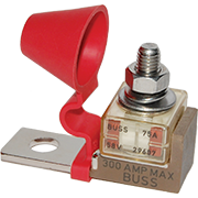
In my situation, the fuse is close to the battery. Even though they are 78 amp alternators, I have never seen the ammeter go that high. They typically after cranking, run a charge from 30 to 40 amps and only for a minute or so. I could go with 100 amp fuses, that is the largest fuse that will fit that holder that I know of.

I have experience rebuilding these Delco alternators. I have about 4 spares.
My alternator wire goes from alternator to helm ammeter to fuse to battery lug in the battery switch.

OEM had run the output through ammeters up on the flybridge. That was a very long run, I cut them out of the circuit and rely on voltmeters for monitoring the power output both on lower and upper helm.

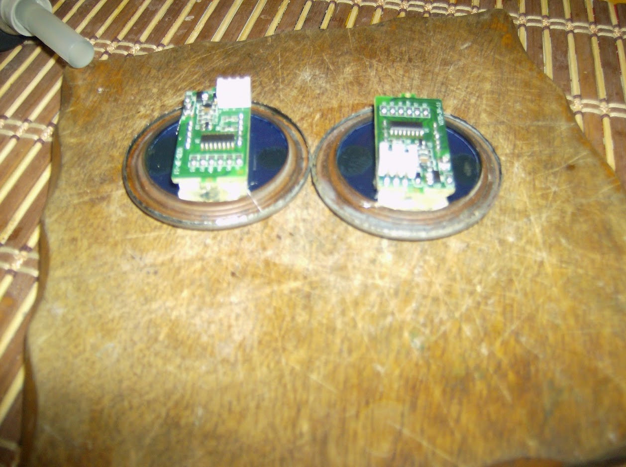
After pulling out the ammeters, to reuse the hole, I gutted the ammeter and put in a 3 wire digital volt meter. The third wire is a voltage sensing wire. Other 2 wires power the meter.

cc-M4IhUEE4SGlM4SSOpNV2RnG927iNYsi3VhGEhTQ6nm_DVx7GiBoVmhMNvJhMR-FAZXnmvWdiE1vLFuy3M8BRXWPy7_5zJuvqxRHrAr4SJd3fBMv5cEdV5fsFaEf_KG0nu9ORf0p_2Xc-rR2r8E18wQ2CXat03sliDk5_zU2faWS9fQeIaQ29bhlwG5d9Jq3ZQndNRZ6Y3BzD0DS4ztfQVNSBZNURJuZtnWrwgrP9GhRFKAmIaLP11syjkZvGEX5gk8jIyFXfWi7GVY3SvmnAftyTb7bCAxfElIHDhDghE4YoX-ehzcHHubnH7YGsKY8h4xgrABo_8Dg7zN2LhcOktJ7XLzMQ-pLDQG40KAMeDDt6Ev8ulXviNACODR37-NaIkGDyFniauWCMWvw7tah12W23HfjQvSJnoPzjAmpsIt-9vp9oK4vOnVRTT_s0rlLLI7phWywFCrUnvMlQycK6Gpnmt5cOWKuWHYY66WZPVT_pwuqOJi5t0ag89ai6aKn4G-Qj7fQs0BwQ0XoLcDdVVZ7zdf96-MeRGMEYxg2Rj-_s0ZX_l1jDUyje9Psoi6oH7=w1259-h938-no

ls3ODBBMy3rzEVtQ0fgrOaGGmQslw6loQc20jbP6lPbKnYaeETevljqQGrTiBMwh_1LPhiBj3Aaddt10POG1vkyNd6N2NYnfOb7yZ2XiCj1l_W1zC6xxC-Mhoe7b_HqkXZDBdHEP8BKpJCJclTt6dR1D1ASLbFioQs99ZAa0prJeOnqXsUtDMaQ-BrVG_eFFF8W_hCT8bYFBLspc2QH9RiXsefMcYBjFDmAPjECt5KEUCPboc2WMAT6gQXSRG9ZHzwrn9L2QtKU5ECPOA2DXI4CLB1ioUdq6-bUBkcavRCBoGxIBQO28skq3bvLF-0rjkCXX-k50de-9v3XFM7htGk_kwG7gLMDCv-pjJFcrVcuALLFD20AH1KNTUrnrXn4NXH8nBEeaMrgxCv8uSWJjRinaNZ2rosSgAYY4pcnxOgjXiMJBAHUgY3RVk4LUuwzeVCcRNweYGz_d_H35roE8tKtYAi2LhwQREjRQd-DwbEz2gxmz-IFybBaP3dMqvnslWVwpKzAUzumSWDalUWlmoXdaH6mOBU51CX5nanTcV-bsRNKZd5FKQtsc7RJFXnjc78W4=w1259-h938-no


Created a black mask, then used some blue plastic to give led a bluer look.
Meter I pulled out of its case and hot glued to the old ammeter face.

NkIuZPEVFnAwxaz00zUZEJuHs985vBiDkdovppdIO0xjZvkEovXa5Ikjg1deqBjB23vyWpF_u25T0XVC1KHYzI08ghdkdfhFc9FvwZitMaOslC8a-mSij9lmTQVyb8HG95wPmcj-fptbL-YHFa9ewF6uEQ3us2GB8dJqruf3Cckm6Z1ZGVShn6IYp8h2qq7tjAsTp4S6KWvxkSOitEf7dhVFD_oZK0sEgz4TcKt6Y9OcZVvmi7uYocW7Lwv4Wr9qJuCo5YupLGva1u_ReRZlYcsKyb1QcPzzNbhzYAVST80Qz8Q1qkHXGCmcBAaVjgeyKjfIeIAXxVMctAgVaqCjVmA79UFYqVTb-PsAq5tOXzsNHQ6t4yZsmoDkcTlFT0sxFteF3Sznn4PPJspPHTzNF6bgX6ZKvCXmP9WOb-oNuCQYnRV8c0VBfYaoUTbOrTuRGR8U5jGsx3rD2FeG0wmv-5GxooHbAgCuvSnnugFeFA1RnAg4hOXWdW7XsGZEHVrhRz0uBy6HmVix_ZTfZBrUw1xFE56ybZuPw0SeaQwgWInewpdynofBq6-9qSaeEifi70pF=w1259-h938-no


The original SW ammeter case has 3 electrical connections built in. I was able to reuse them, so the internal wires from the LED gauge hook up inside the case., all the nuts work just like OEM.
New meter uses a ground, hot, voltage sense wire.
 
Last edited:
My alternator wire goes from alternator to helm ammeter to fuse to battery lug in the battery switch.

Unless your ammeter has an external shunt, and uses voltage sensing shunt leads to the ammeter display, these dash mounted ammeters can induce lots of voltage drop in the B+ wire of the alt.

Voltage drop is quite possibly why you're only ever seeing a max of about 30-40A. If you're talking about a MAXI fuse holder for a 78A alt I would suggest a fuse with the correct AIC to be direct connected to a battery bank. The MAXI has a max AIC of 1000A which is not suffucuent for direct connection to a bank.

A 78A Delco can easily pump out 78A +/- if properly wired, and the bank can accept it. System voltage drop will have it hit the limit voltage and start current limiting considerably earlier. It's not uncommon to see an alt with bad voltage drop hit the voltage limit, at the alt end of the circuit, almost immediately. This limits how much current the battery will accept and we see low alternator output and longer charging times..

An MRBF terminal fuse holder & fuse can be mounted directly to the battery and would allow for a larger fuse. It also has an AIC rating of 10,000A that is appropriate for a battery bank connection.


5191.png
 
An MRBF terminal fuse holder & fuse can be mounted directly to the battery and would allow for a larger fuse. It also has an AIC rating of 10,000A that is appropriate for a battery bank connection.


5191.png
That is what I used on my new bank to protect all the wires connected to the battery. Simple and effective.
 
Back
Top Bottom