The Fuel System Upgrade Project

The friendliest place on the web for anyone who enjoys boating.
If you have answers, please help by responding to the unanswered posts.

Tom.B

Moderator Emeritus
Joined
Jul 30, 2009
Messages
5,839
Location
USA
Vessel Name
Skinny Dippin'
Vessel Make
Navigator 4200 Classic
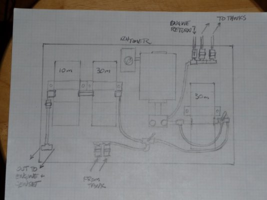
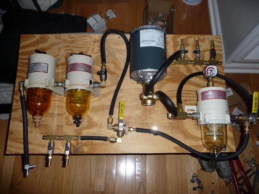
I wanted to start a new thread to have a single point of reference to chronicle and ask questions in regards to my current fuel system upgrade project. As posted in the fuel polishing thread, I am going to reconfigure Skinny Dippin's entire filter rig to be a multi-stage filtration and add a simple fuel polishing circuit.

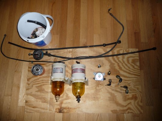
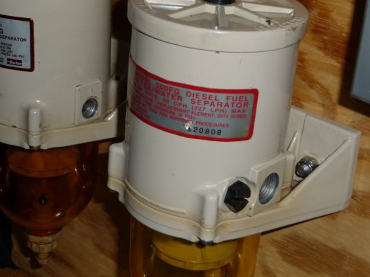
The current system (I had pics, but the camera got stolen with them in the card) was two Racor 500 filters (and an Algae X). One filter was dedicated to the main engine and the other for the genset. The return line from the main engine dumped into one tank and the genset into the other thru 1/8" (or 3/16") fittings.

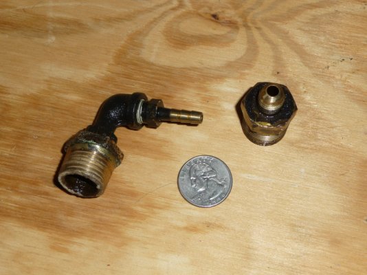
I spent this weekend dismantling the old system and now have a pile of parts in the dining room. It, of course, can apart very easily. Now the hard part begins.

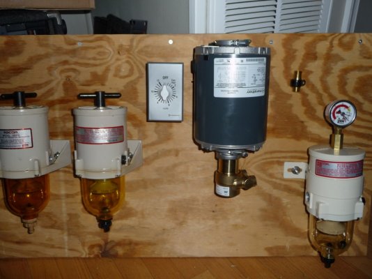
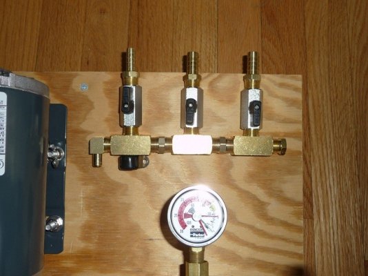
The plan is to mount the entire system to a 1/2" piece of Starboard 20"x35" for easy removal and service. Currently, I have received a new Raycor 500 from Defender and a 1/4 horsepower A/C motor, Procon 60 gph pump, and a check valve from Grainger. I have also found two hydraulic shops (one here at home and one down at the boat) that have warehouses of parts and the willingness to help with my project.

I'll take pictures along the way and hope you guys can offer up some good advice.

Thanks,
Tom-
 
Here are a few pics.

1) The final-ish drawing.
2) The pile of parts removed Saturday.
3) The two tiny returns.

-- Edited by GonzoF1 on Monday 31st of January 2011 09:37:33 AM
 

Attachments

  • p1000048.jpg
    p1000048.jpg
    184.4 KB · Views: 104
  • p1000043.jpg
    p1000043.jpg
    163.1 KB · Views: 108
  • p1000055.jpg
    p1000055.jpg
    96.1 KB · Views: 126
Here is the mock-up on plywood. The plan is to take it to the hydraulic shop all mounted and spend an hour or so plumbing it up.
 

Attachments

  • p1000056.jpg
    p1000056.jpg
    155.5 KB · Views: 102
The next step was to spend today cleaning and rebuilding the old 500's. They were pretty filthy and whomever worked on them last must not have been reading the directions. One ball valve seat was completely gone and the other was installed backwards. But, nevertheless, a little elbow grease and Dawn liquid soap did the trick.

Then I went to Ace Hardware and got some 1.25" stainless bolts and locking nuts and mocked them onto the plywood. I may have to redesign the mounting because it won't be easy to take them off the board in the future without taking the board down completely to get a wrench behind it (something that should be easy to do), so I may think on that a while.

I do have a question: This rig (in order to save some cash) has three different model year filters with three different configurations of drains and ports. Nothing REALLY major EXCEPT that on two, there are two different size in's and out's. Anyone see an issue with this? (noted in picture #3)

Pic 1) Mock-up
Pic 2) Fresh and clean filters
Pic 3) One has 3/4" 16 UNF (whatever that means) and the other has 3/8"

Tom-
 

Attachments

  • p1000063.jpg
    p1000063.jpg
    148.2 KB · Views: 105
  • p1000064.jpg
    p1000064.jpg
    131.1 KB · Views: 99
  • p1000066.jpg
    p1000066.jpg
    119.4 KB · Views: 97
I see no issue with the different size ports. Once you have adapters in pace it will be invisible.

If you are going to use Starboard in the end product, *why not simply tap the* mounting holes.
It should be strong enough to support the filter units.

Or if you insist on thru bolting with nuts, make some "stand-offs" so the mouting board has a space behind it to get a wrench on the nuts.

OR...use "carriage bolts" (the ones with a square under the round head) from behind and draw them into the starboard...they will stay in place that way. The nuts will be on the outside.
 
Port size is a non issue as your flow rate is only 1 gallon per minute. The ports should easily support 3/8" or 1/2" fuel lines.

Ted
 
Tom,
I think the mockup is a great idea. Where did you source your timer from?
 
Forkliftt wrote:

Tom,
I think the mockup is a great idea. Where did you source your timer from?

Timer, pump, motor, and check valve are all Grainger.

I'm heading to the hydraulics warehouse tomorrow to start the plumbing.
biggrin.gif
 
jleonard wrote:

I see no issue with the different size ports. Once you have adapters in pace it will be invisible.

If you are going to use Starboard in the end product, *why not simply tap the* mounting holes.
It should be strong enough to support the filter units.

Or if you insist on thru bolting with nuts, make some "stand-offs" so the mouting board has a space behind it to get a wrench on the nuts.

OR...use "carriage bolts" (the ones with a square under the round head) from behind and draw them into the starboard...they will stay in place that way. The nuts will be on the outside.

Thanks for the tips. I thought about stand-off nuts. I'd have to use a combo of carriage bolts and stand-off because I feel the need to use nylon locking nuts to avoid them backing off. But, at 7 knots, there isn't TOO much vibration down there. Still, anything worth doing is worth over doing.
wink.gif


We'll see where I end up. I have many step to take before I get there.
 
*"nylon locking nuts"

Just use a dab of loctite. You'll be buying some (most likely) for the fittings , use it for the nuts too.
*
 
Well, the hydraulics store(s) was kind of a bust. While they can get some of the parts and have some in-stock, they don't really provide the one-stop solution I was looking for. Soooo... looks like it's time to hit the Grainger catalog and do most of this myself.

I have a few questions.

Should I just stay 3/8" I.D. for all the fuel lines? I was thinking 1/2" for the polishing side, but I would like to keep it consistent throughout the entire system so I don't have to carry two different size spares. Although, the line from the tanks will probably be 1/2.

Should I look for the hose barbs to be extra long to allow for double clamps?

I have had the hydraulics guys try to sell me on "Push Lock" fittings. They don't require clamps as they have two large barbs that lock onto their hose. They hold more psi than my system can provide and cannot be pulled off. They must be cut off. I am not an expert, so I don't know if this is common on boats.
 
GonzoF1 wrote:


I have had the hydraulics guys try to sell me on "Push Lock" fittings. They don't require clamps as they have two large barbs that lock onto their hose. They hold more psi than my system can provide and cannot be pulled off. They must be cut off. I am not an expert, so I don't know if this is common on boats.
If you use Push Loc fittings, they should only*be used*with*Push Loc hose.* Is the hose USCG approved?

*


-- Edited by Larry M on Thursday 3rd of February 2011 02:08:35 PM
 
For nuts take a look at " Tee nuts" available in SS if you like. they are an ID threaded mushroom shaped insert which is put the hole in from the back side of the wood, a couple of prongs sink into the wood and keep the insert from turning when the bolt is screwed in or out. The bolt is holding in metal yet the back of the boart is virtually flush.
http://www.boltdepot.com/t-nuts.aspx I have seen them at Lowes also

Steve W
 
Is the Shields fuel hose sold at West Marine acceptable to use for this rig?

(Grainger fittings and stuff on order
smile.gif
)
 
Have you considered adding a squeeze bulb priming system? I added multistage filtration by adding a canister type (looks like an oil filter) fuel filter plumbed in series with my Racor 900 filter. Adding squeeze bulb priming made priming the engines after a filter change a breeze and eliminated the necessity of carrying fuel to refill the racor.

-- Edited by timjet on Friday 4th of February 2011 10:37:58 PM
 
timjet wrote:

Have you considered adding a squeeze bulb priming system? I added multistage filtration by adding a canister type (looks like an oil filter) fuel filter plumbed in series with my Racor 900 filter. Adding squeeze bulb priming made priming the engines after a filter change a breeze and eliminated the necessity of carrying fuel to refill the racor.

-- Edited by timjet on Friday 4th of February 2011 10:37:58 PM
No need. Gravity does fine. Just need to crack the tank valves with the filter top off and it fills up easily.

*
 
With 1/2 full tanks I doubt that your tanks have enough head to fill the on engine filter. That is the purpose of the squeeze bulb - to fill the on engine. On my Perkins the hand lever on the*lift pumps do this job.
 
No need. Gravity does fine. Just need to crack the tank valves with the filter top off and it fills up easily.
Ditto!

*
 
The Man-Fairy (UPS guy) came today and brought brass fun!

1) Box of items from The Man Bible!
2) Mocked-up intake manifold.
3) Looks like the total mock-up reveals that I might need a little bit more space.
4) One concern I have is that the barbed end of the 90-degree end (on this output manifold) is a tad short. It will take some testing to see if it needs redesigning.
 

Attachments

  • g1.jpg
    g1.jpg
    116.6 KB · Views: 96
  • manifold.jpg
    manifold.jpg
    89.6 KB · Views: 109
  • mockup1.jpg
    mockup1.jpg
    112.2 KB · Views: 110
  • manifold2.jpg
    manifold2.jpg
    102.5 KB · Views: 103
Tom,If you are talking about the 90 degree fitting on the left I agree. Why not use a male/ female 1/4" NPT brass fitting, then screw in a barb fitting the same as you have on the valves?
 
Latest mock-up photos below.

Here is the latest question: With my limited experience with these fixtures in such a specialized application, how do I get it all to "line up" to the proper orientation? My worry is that the valves and pipe fittings are either too tight or too loose and not facing the correct direction to be useful. Any tips?
 

Attachments

  • mockup2.jpg
    mockup2.jpg
    121 KB · Views: 63
  • mockup3.jpg
    mockup3.jpg
    107 KB · Views: 63
Oh, sorry... Forgot to mention that this is just a bunch of cheap-o 3/8 hose from O'Riley's ($1.11/ft.) for mock-up purposes ONLY. I certainly didn't want to spend four or five bucks a foot on the real stuff until I knew what lengths I need. Don't worry... Will goto West Marine (or Defender) once I am ready for final assembly.
 
Phew!

The valves look fine, although I can't make out the orientation of the 3 way.
 
Delfin wrote:

Phew!

The valves look fine, although I can't make out the orientation of the 3 way.

Which one? The bottom one routes incoming fuel to filter circut or polishing circut. The one on the far right is a bypass for the polishing filter to use only for fuel transfer.

Unless you mean sexual orientation. In that case, the 3-way is OBVIOUSLY bisexual. DUH!
biggrin.gif
 
It looks fine, I just couldn't see where the arrows were pointing on the 3 way.* And I am fully in support of equal opportunity for LGBT freedom in plumbing supplies.
 
Ok, cool... So can we see if anyone can answer my question?
smile.gif


"With my limited experience with these fixtures in such a specialized application, how do I get it all to "line up" to the proper orientation? My worry is that the valves and pipe fittings are either too tight or too loose and not facing the correct direction to be useful. Any tips?"
 
<table cellpadding="0" cellspacing="0" class="forumline borderline table" style="width:100%;"><tbody><tr><td valign="top" class="row1 borderline" style="text-align:left;"><table style="margin:0px;width:100%;padding:0px;"><tbody><tr><td colspan="2" style="width:100%;">
</td></tr></tbody></table></td></tr><tr><td colspan="2" class="row3 row3text borderline"><table cellpadding="0" cellspacing="0" style="width:100%;"><tbody><tr><td colspan="2" valign="middle" style="text-align:right;">forum.spark?aBID=115492&p=3&topicID=40858124&page=1&sort=oldestFirst</td></tr></tbody></table></td></tr></tbody></table><table cellpadding="0" cellspacing="0" class="forumline borderline table" style="width:100%;"><tbody><tr><td valign="top" class="row1 borderline" style="text-align:left;"><table style="margin:0px;width:100%;padding:0px;"><tbody><tr><td colspan="2" style="width:100%;">With my limited experience with these fixtures in such a specialized application, how do I get it all to "line up" to the proper orientation? My worry is that the valves and pipe fittings are either too tight or too loose and not facing the correct direction to be useful. Any tips?"


</td></tr></tbody></table></td></tr><tr><td colspan="2" class="row3 row3text borderline"><table cellpadding="0" cellspacing="0" style="width:100%;"><tbody><tr><td colspan="2" valign="middle" style="text-align:right;">forum.spark?aBID=115492&p=3&topicID=40858124&page=1&sort=oldestFirst</td></tr></tbody></table></td></tr></tbody></table>"With my limited experience with these fixtures in such a specialized application, how do I get it all to "line up" to the proper orientation? My worry is that the valves and pipe fittings are either too tight or too loose and not facing the correct direction to be useful. Any tips?"

If the fittings are NPT you won't get them "too tight". And as I said before if you use loctite 242 (or equivilent)*the fittings won't leak. Even if they are not cranked in very tight.

-- Edited by jleonard on Friday 11th of February 2011 06:21:22 AM
 
Permatex Threadlocker Bule... Same thing or no?
 
Back
Top Bottom