DIY engine monitoring system

The friendliest place on the web for anyone who enjoys boating.
If you have answers, please help by responding to the unanswered posts.
I'm interested, and the wife is a software engineer.... I'd like to monitor the specifics, set alarms, and keep logs of the basics for the 2 engines AND the generator.

I had been thinking of some of the off-the-shelf devices like the NoLand and plug the datastream into an iPad running iNavX.
 
It's Alive

So far this has been a very simple build and is within the grasp of most people who can solder and do things like install device drivers.

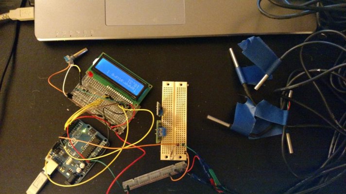
The LCD display arrived and I started wiring/coding. At the moment it cycles through the temperature of each of the five DS18B20 temperature sensors and displays the values on the LCD. Next step is to integrate the momentary button to toggle through the measurements manually or stay on one sensor. Attached is a pic with the breadboards. The RPM sensor and K-type thermocouple are on a separate bread board and I'll wire/code them in the next few days.

Some thoughts on the temperature sensors... The DS18B20 is about $2 and can handle up to 250f. It's also very compact and they all share a single, common data line. Each has its own address, like an IP address so the code just queries each one for it's temperature. You can have as many as you like in theory, but I'm staying with five:
  • Raw water temp in
  • Raw water temp out
  • Coolant entering the heat exchanger
  • Coolant exiting the heat exchanger
  • Cylinder head temperature

The sensors come in two forms: either the bare chip, or an assembly that has the chip embedded in a stainless steel probe with 6 - 10 feet of wire. Both forms are cheap - I purchased a set of five assemblies with 10 feet of wire for <$20.

But I think the bare chip is better for this project. I plan to drill-out a few drain plugs and embed the chip in the plug with high-temp epoxy.

For temperatures that exceed 250 I'm using a k-type thermocouple that can go over 1200f. So far that's just the EGT, but I'm not sure if oil temp could get high enough to destroy a DS18B20.

Does anyone know if oil temp exceeds 250f?

There is also a red LED and a buzzer for alarms. If you plan on building the project you would need to go into the code and set your alarm thresholds. There would also need to be a "Silent" button to suppress the alarm for some number of minutes.

I'll create a bitbucket account and put up all the code, schematics, instructions, and laundry list.
 

Attachments

  • a.jpg
    a.jpg
    116.4 KB · Views: 146
  • EngineMonitor.txt
    2.1 KB · Views: 107
For those interested in wireless, SigFox is an alternative to the 3G/4G network and is being setup across the world. It is currently running in the San Francisco bay area, however I do not have the specifics. SigFox is like wifi for the internet of things. It's a mesh-style network and supports very high volumes of small messages.

This is the ideal way to get real-time access to your boat while it's at the dock. There are SigFox shields for Arduino on Amazon.com, and Amazon hosts an IoT service. I believe the way it works is similar to a peer2peer network with various gateways, like to Amazon. One could spin up an IoT service at AWS and start collecting data on his boat in real time and then run analytics at any point. Or get alerts when the voltage dips or the bilge pump turns on - without going with an expensive and/or proprietary vendor.
 
RP, why not get really fancy and link a yellowbrick to it and have satellite coverage?

oh, the monthly bills... something like 12 cents a packet.

Oh, never mind ;)

stu
 
Not to be a spoil sport, but without a doubt I am, I have a hard time seeing the actual value of the enhancements you are doing to your engine: changing the cooling flow path, adding a Chinese fuel flow measurement system and now this home brew engine management system.


The Perkins in your boat is one of the simplest marine engines made. It will run for thousands and thousands of hours with just basic maintenance. If it does develop a problem it will be mechanical and the above electronic systems aren't going to help much. You will need hands on seat of the pants diagnosis to get to the bottom of any problem and skill with mechanical tools to fix it.


The electronics you are talking about adding won't tell you much more than standard engine instruments and the manufacturer's prop power and fuel consumption curves.


I took a very different approach to my first real cruising boat about 25 years ago. I had had my run with soldering irons, microprocessors applications, machine language programming, etc.- all for fun and not work. So I set out to learn the mechanicals of marine diesel engines- how they work and more importantly how they sometimes don't work and how to make them work right.


But I do sort of understand the charm of developing something geeky to work with your new boat toy. Just make sure that the geeky fun doesn't get in the way of using your boat. They are made to be used aren't they?


David
 
The crab season is closed so I need to find other ways to enjoy the boat.

To give a little background,

Many years ago I owned a 1965 Evinrude 60HP engine. It had a huge engine with four cyclinders. The distributor was on a hinge and a lever would swing it forward as the throttle advanced. The ignition advance should have been set based on RPM, plus have a retard for starting. And the mechanical parts had a lot of play in them as well. It ran well, but hesitated when accelerating and was sometimes hard to start. So I built a distributer-less, fully electronic ignition using a PIC microcontroller for it. There were no moving parts and the advance map was programmed into it, and there were two large capacitors and a giant mosfet. The OEM ignition remained in its place in case I needed to switch back to the stock ignition. Afterwards the engine ran impeccably. Always started after half an RPM and accelerated much better. I have failed at many projects, but this one worked and convinced me that modernizing engines can sometimes workout well.

But I agree with David in principle: the engine is simple and the basic gauges should be adequate. The boat only has engine temperature, oil pressure, and voltage gauges. There are no alarms and there is no idiot light for the oil. And the tachometer reads about 10% too low and is non-adjustable.

For 1978 standards I'd say the boat lacks at least an oil light. More information is usually better. For example, when I welded up a new SS wet elbow I added a bung and EGT. Now I know my EGT is normal.

Current power plants typically include a thermocouple at the raw water exit on the elbow for an alarm.

My raw water system was on the verge of becoming dangerously plugged. The exit temp was around 140 and this was determined using an IR scanner.

Having the raw water temps, accurate tach, engine room temp, EGT, and oil temps all seem high value.

I'm doing this for the fun of it and based on the survey response almost everyone else is too. From a Maker perspective it's fun, cheap, and high value. The alternative Arduino projects are typically toyish.

I think a better perspective is: I want to work with an Arduino and I have an older boat so let's build this monitoring system.

Regarding the cooling path - this is something many other owners of the engine type have done and many consider it a best practice. I have not done the modification because I do not know the future cooling needs of putting the iron exhaust manifold into the freshwater circuit.

You may be entertained to hear that I'm analyzing the CAV DPA for ways to computerize it - like I did to the old Evinrude. It's way down on my list though, since the engine runs nice and smoothly. I would be interested to know if I could increase the efficiency or reduce emissions with a microcontroller. I'm not interested in the complexity of a common rail system, but if a servo, controller, and gas sensor could make the system better then I'd like to know how.
 
Thanks for taking my somewhat critical posting in an equanimous spirit.


With regard to computerizing a mechanical injection engine, it has been done by Yanmar, Cat and others as a transition to common rail to meet EPA Tier X regs, but to really work you need to get into the guts of the injection pump. That is one place I want to stay away from.


Since diesels can operate at a wide variation of fuel/air ratios, unlike gasoline engines, I don't think there is much to be gained by tweaking mechanical injection.


Common rail injection uses higher pressure which improves the spray pattern and often multiple pulses per injection cycle which distributes the fuel better over the combustion period. That is how they achieve better combustion and marginally better fuel economy. You can't duplicate that.


David
 
The code and schematics have been posted to BitBucket at https://bitbucket.org/R_P_Ryan/enginemonitor/wiki/Home

I am still working on some of the code. Also, I am still waiting for the thermocouple amplifier boards and the last DS18B20 sensor to arrive. These are not yet implemented.

I have not yet included to code for the RPM sensor.

There is enough code and documentation to order the parts and start wiring things up. I recommend wiring everything on a breadboard and getting the components working with the code before soldering.
 
You may or may not get a lot of thanks on this project, but let me absolutely assure you that I, at any rate, am in awe at the work you are putting into it. It is really appreciated!
 
Thanks John! I'm doing it mostly for the fun of playing around with electronics and software. If it can be useful, well that's just a plus.
 
I just discovered this thread after speaking with Remwines. First off I must say, nice work! I admire your skills and knowledge of electronics and your willingness to share in an open architecture to make it available to peers at no profit. Kudos to you!

I have a 1977 tub with twin 4.236 Perkins without an alarm on the boat! I have 'full instrumentation' at both helms, but it's analog and mechanical. My FB oil press gauges are electric Stewart Warners but my lower helm SW oil press gauges are driven by mechanical, oil-filled capillary tubes. I have electric upgrades in boxes awaiting installation but that's on a back burner. Part of this delay is because I think I should add a monitor with alarms to alert me to problems.

I love the concept of using off-the-shelf components to piece together a system to provide early warning of impending failures. My initial impression is that the price is attractive, but my concerns center on reliability and robust construction for the maritime environment. I understand it's a DIY kit designed for anyone with moderate skills and knowledge, but it would be self-defeating if its hardware components failed rendering the engine inoperative.

Also, being a modular and expandable design, it needs to provide ample capacity for future expansion. With that comes future uses which can make the equipment shift from "nice to have info" to "must have for safety" ... much like our electronic chart plotters have become indispensable. If it's indispensable, it should be near indestructible.

I love djones44's iPad enclosure. I think using an app to present the results via iPad or Android tablet makes the best use of current technology and lower pricing for truly functional displays. Having a screen of numbers scrolling by on a small LED display is less than optimum for processing lots of data. I had to do it on my job for years with old technology. We got by, but the advent of graphic displays made it a cinch to detect the data abnormalities.

Imagine vertical tapes of digital readings with all normal values shown in a straight horizontal line across the display. When all is normal, all the lines segments form a continuous dashed line across the display. Any values out of the norm would jump out at you as a break in the line continuity. All Normal values present in Green, Abnormal Warnings in Yellow and Emergency Shutdown values in Red. In this type of display, the value of the data point is not as important as its variance from the norm.

fuel-guage-in-citation-500-ser_11333347.jpg


So if I can build an affordable, robust box that will stand up to the rigors of ER life that provides me with essential engine and environment data and displays it graphically via wifi to my devices, I'm aboard. Otherwise, I might as well just have dumb analog horns that sound when a value is exceeded. At least they're cheap and reliable.
 
Last edited:
Networking is for the next version. I'm looking for feedback on which protocol to develop first. So far here are the choices I'm aware of:
  • NMEA
  • SignalK
  • WiFi with a webpage
  • Wifi with JSON
  • Bluetooth
  • Ethernet

FlyWright, regarding safety you're right-on. I omitted warnings and alerts for the very reason you point out. But I would say the reliance on electronics on a boat can create a false sense of security. Recreational boating is a very different environment than flying an aircraft - it has a much lower barrier to entry. Marine electronics help paint a picture of what's going on but wholesale reliance on them is asking for disaster when a recreational captain is at the helm.

Obviously a home-made monitoring system is not to be relied upon and this has been made clear. In light of this, the Arduino platform is very robust and battle-tested. They ship over 10,000 units per month so the bugs have been worked out. The base components are very reliable and marine-grade thermocouples can be used if desired.
 
When this thread first began, I had never heard of an Arduino board. But it all sounded interesting, so I looked them up, read about them, ordered a couple, and did a few small projects. So I feel up to speed on them now.

All that also awakened a dormant interest (been about 10 years) in PIC programming, so I did some research on the current state of that. Seems that the MPLAB IDE X is very good, as is the XC8 compiler. So I hauled out an old ICD-2 from storage, found a few 18F PICs which may still be good, and am going to play with PIC programming again. When I started with that in about 2003 I programmed them exclusively in assembly language, but will now switch to C. I love assembly language, but have to admit that C is more convenient. Reminds me of the old saying: "Candy's dandy, but liquor's quicker."
 
So I hauled out an old ICD-2 from storage, found a few 18F PICs which may still be good, and am going to play with PIC programming again. When I started with that in about 2003 I programmed them exclusively in assembly language, but will now switch to C."

Assembler programming on a PIC processor is like pulling out pubic hair with vice grips... There are lots better processors out there than PIC. Been there, done that, burned the tee shirt.

Try Atmel or something similar... Or even Raspberry Pi.

Just my 2c worth

stu
 
Very interesting thread.

I started working on something similar with Arduino about a year ago, but have presently got my attention focused on building a home automation system for our new home that we are building this year.

I am then planning to get back to my boat monitoring project, so will be watching your project with interest. I will also try to contribute where I can.

Cheers,
Mike
 
Last edited:
p.s. I should add that I have a SignalK iKommunicate (from Digital Yacht) device coming in April/May this year. I was planning that anything I develop would use SignalK to communicate with various devices on board.

-Mike
 
Are there any decent SignalK apps for the iPad/Android? From what I've read about SignalK it uses JSON over HTTP, which would be easy to publish from an embedded web server. The only issue I see is the need for an onboard wifi router as the Arduino wifi shield does not work as an access point.

There's also the serial output from the USB, which could be connected to a PC where it could be graphed. For networking I'm thinking the addition of a RaspberryPI might make sense since it would be easier to interface with several networks like NMEA, bluetooth, wifi, and even ChromeCast to push the data to your flatscreen. It even has DVI, so it could be cabled directly into a monitor.
 
Hey RP, with a raspberry pi, there is a HDMI video output and you can add a USB wifi radio. I added a USB wireless keyboard from logitech, and powered the whole rig off the USB port on the TV. All I have to do is switch the TV over to HDMI4 (which was free at the time) and I have access to the raspberry pi... If the TV is on, there is power on the USB port. If you want to keep it live 24/7, you can power it from any other USB 5v source (there are some plug in devices with batteries too) which act as a UPS for the Raspberry pi computer.

Once signalK is in production, you should probably be able to get linux open source code to talk to it.
 
I find the following set up simple and it will cover most important functions. An exhaust pyrometer and a simple inexpensive exhaust hose contact temperature alarm. For boats with turbos the pyrometer can be a combo gauge with boost pressure. A vac. gauge on fuel filter with a captive needle to show highest reading. For those with a higher level of paranoia an IR gun and routine engine scans of critical areas. I find complicated systems that try to monitor too much problematic.
 
WiFi has arrived

Version 2 was much simpler than I thought. The Arduino connects three pins to three pins on the Raspberry Pi. There's a voltage shifter to adjust the Arduino 5v to the RPi 3.3v, but that was already in place for version 1. So it was really just a matter of loading some software on the RPi and connecting a few wires.

After that I just wrote a small python script to get the values from the GPIO pins and render them in a web page.

I'm not much of an HTML artist, but I can imagine an icon of a motor with the measurements displayed in different places.

Attached is an image of the output on my iPad. I think I'll play around a little with SignalK and returning a JSON string under a different path. Does anyone know of any SignalK apps?

I also need to put the Raspberry Pi in Access Point mode, so it can create the WiFi network thus eliminating the need for an onboard router. Thanks for the encouragement.

Robert
 

Attachments

  • WiFi.jpg
    WiFi.jpg
    65.4 KB · Views: 144
Feeling like my two worlds are colliding in this post. Very cool. Following and hope to contribute if I can clear some time.
 
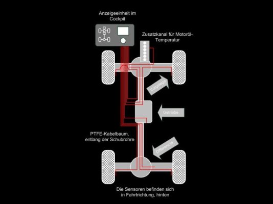
A more serious application for this project would be a control system for drive line temperatures on heavy duty 4x4 like a Mercedes Unimog.
 

Attachments

  • gearbox-diagram.jpg
    gearbox-diagram.jpg
    33.8 KB · Views: 81
It's very simple to add on a high-voltage, high-amp relay to the Arduino. There is also a high-power PWM motor controller shield. These two shields are sitting in my electronics box looking for a project.
 
mixing high and low voltages?

It's very simple to add on a high-voltage, high-amp relay to the Arduino. There is also a high-power PWM motor controller shield. These two shields are sitting in my electronics box looking for a project.

I would attempt to keep the high voltage away from the Arduino if possible and only control the relay with a low voltage (below 5vdc) lead. Perhaps this is what you're planning to do.
 
It's a toy sitting in the box with no project in mind. Once I got the basics of the Arduino figured out I thought I'd need these relays for something. Nothing yet to actually control at this point, just monitor.

The sailing folks have done a ton with this sort of stuff, even setting up an Arduino auto pilot. I don't yet have that kind of faith though.
 
Feeling like my two worlds are colliding in this post. Very cool. Following and hope to contribute if I can clear some time.

Not colliding. Merging. Me too. :) Right now, I am mulling over the possibility of avoiding the very irksome job of running wires from the saloon up to the bridge, and doing it with wireless instead. Just fun, of course, but I see some very distinct possibilities. The nice thing about all this is that (a) for much, much less than just one boat dollar you can do all sorts of cool things, and (b) the more you delve into it, the more you see things which are possible.
 
Last edited:
The WiFi-enabled version 2.0 wiring diagram and notes are published at https://bitbucket.org/R_P_Ryan/enginemonitor/wiki/Version_2_0, however version 2.0 is still work in progress.

There are some cool javascript gauges that the Raspberry Pi can serve up.

I took a close look at SignalK and it requires some complex messaging. That, coupled with the lack of SignalK apps made me keep the system as HTML/JS. I scribbled together a python script that returns the values in JSON but making them SignalK-compliant was more effort than I thought was worth it.
 

Attachments

  • gauges.png
    gauges.png
    34.8 KB · Views: 82
  • EM2_small.jpg
    EM2_small.jpg
    102.9 KB · Views: 140
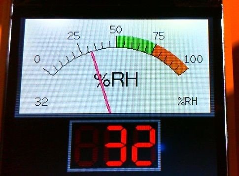
If you integrated a TFT LCD its possible to use it as display for analog displays. For example the 2.2" ILI9341 based 320 x 240 pixel TFT, these are available at low cost on the internet.

Every engine control system needs a watchdog..... after a while people tends to wait for a buzzer signal to be alerted about a problem. When the program loop crasheds this signal will not come......

Why not use the W-connection for RPM, in that case you also control if the V-belt is broken.. In case of a Hall sensor it should be mounted on the alternator for this reason.

Example of an analog instrument on a TFT.
 

Attachments

  • analog.jpg
    analog.jpg
    33.9 KB · Views: 85
I've been looking at the low cost TFT displays, but I think with all the iPads out there it seems redundant. The tach on my boat runs off the alternator and it's totally inaccurate, which is why I've added the hall sensor. I think I've seen some amperage sensors that clamp around a wire to sense current. If so, this could be easily added to both the alternator and the main battery bank. It could show the output of the alternator and whether the bank is net drawing or charging.
 
Some sensors have induction rings that you slip around one conductor and feed you a proportional voltage based on the amount of current going past. Or you could put a shunt in the circuit which will do the same thing but is a fixed device.
 
Back
Top Bottom