DIY engine monitoring system

The friendliest place on the web for anyone who enjoys boating.
If you have answers, please help by responding to the unanswered posts.
Assuming we have agreement on the V1 feature set I'll search for display enclosures

I'm developing a marine enclosure for the iPad, here's crude pics of it; I contemplate it working best as an integrated flat controller. My concept is that this (Poort enclosure) form factor can replace a lot of the traditional dash and display devices, as the migration to tablets continues. A $50 enclosure and an old iPad are a possible platform you can leave in place. Getting the engine sensors incorporated will be a major hurdle. - Dwight

Poort-Prototype.jpg


Poort-Proto2.jpg
 
Last edited:
iPads don't work well in direct sunlight. If you do this for a flybridge, make sure to make a sun shield too. Perhaps a polarized screen protector will help in bright light?

I know my iPads of different generations are poor reading in a car unless you're far from the window.

Stu
 
Is an arduino device stack going to survive in a hot engine room with the other airborne contaminants like salt water vapor, oil, etc.?

While this may be a fun start at a m&c system, people will start depending on it... So we need to think operational durability up front.

Is there an environmental case for the Arduino stack? I am not comfortable with the end user having to connect tinned wires to each board and then stack the devices back together. I would say that there should be pigtails that lead to a connector strip on the outside of an environmental case, and all sensor connections would be connected outside the case. Or have some weather tight gland to seal the wiring as it comes into the connector strip.

You should also plan on sensing battery voltage on one or more banks.

Stu
 
I am interested and have subscribed (I have an arduino onboard as an inexpensive weather system interface - works well).

Have you considered using the arduino for sensor/device interfacing only, with a consolidated data stream to a pc/laptop? A small companion program on the PC would allow a lot of flexibility in display and data logging / trending. Low power laptops are pretty inexpensive. (I have even picked up a number of free ones once they are no longer of use in the business world). For futures, the arduino data stream could be NMEA 0183 - pretty easy for the arduino to do.

An interesting project. Thanks for posting!
 
Is an arduino device stack going to survive in a hot engine room with the other airborne contaminants like salt water vapor, oil, etc.?

While this may be a fun start at a m&c system, people will start depending on it... So we need to think operational durability up front.

Is there an environmental case for the Arduino stack? I am not comfortable with the end user having to connect tinned wires to each board and then stack the devices back together. I would say that there should be pigtails that lead to a connector strip on the outside of an environmental case, and all sensor connections would be connected outside the case. Or have some weather tight gland to seal the wiring as it comes into the connector strip.

You should also plan on sensing battery voltage on one or more banks.

Stu
I totally agree on the right kind of case for the arduino stack. I was thinking there would be terminal block on the outside, like this: http://www.pcb-terminalblock.com/photo/pl1750076-single_level_barrier_pcb_terminal_block_right_angle_pitch_9_525mm_300v_20a.jpg

As for the project box, it should be a sealed unit. The terminal block above would be fastened and gasketed to the outside. The screw-on connections would be on the outside of the box, and the terminals would be on the inside of the case. Those terminals could be soldered in to the stack.


Here is a diagram of the proposed V1:

In addition to battery voltage, what other simple senors would you like to see in V1?
 

Attachments

  • Version 1.0 (1).jpg
    Version 1.0 (1).jpg
    66.6 KB · Views: 100
Lot's of great questions and points. My responses are in line

The opto-isolation will prevent any accidental 'let the smoke out' events when power from another source gets into a sensor wire.

Wiring should be high temperature (insulation) since any accidental contact with exhaust manifolds, etc. could result in shorts which could smoke the D/A shield.

I'm thinking plenum-grade CAT-5

When you say raw water in and out, I assume temp and not water flow?
Yes, but I've seen some cheap flow sensors that report volume, but I doubt it's marine quality

you also may want to consider a temp sensor on the shaft seal (packing temp).
Great idea, Would you recommend this in V1? Would be easy with a 1-wire sensor since it woudn't take more pins

Also, a temp sensor for engine room? fire sensor?
Engine room temp is included in V1. Not a fire sensor though. I was thinking a subsequent version but we take something off of V1 to accommodate the fire sensor. A small concern I have is when this system starts to take the place of what should be a proven marine grade system, like a fire alarm or carbon monoxide tester.

And you may want to make the provision available for twin engines (two arduino)

plan on being able to log data points to be able to create a "normal" for each sensor. That way, you can quickly see a rising / falling trend and sudden out of normal data ranges.
I'm thinking alerting is in Version 2, but that's only because I want to have something simple and easy for the first version to increase adoption. Using the data for alerting or logging is very valuable, but is a bit more complicated since it involves a configuration capability and storing a map of data to determine the trend.
I'd like to have a data logger capability in some future version that stores all the measurements, with a timestamp onto a flash card


I will see if I can get the code for an old compiler / macro language I wrote many years ago. I think I could adapt it to be able to do ad-hoc coding.

What OS will the Arduino be running? What dev kit would you start with?
The beauty of Arduino is there is no OS to concerned with. You just plug the board into your PC/Mac/Linux using a USB. Then you deploy the code to the arduino using an open source tool that is downloaded from the Arduino site. This is the same tool you can use for your IDE, so it you want to see the code or even change it, it's simple. As for the dev kit, I was thinking just the Uno board ($25)


My son in law is an arduino & android developer (current) and I'm ancient developer from DOS, OS/2, Windows, and a bit of IOS development lately. i think this would be a fun project and would enjoy tinkering with it.
With your DOS through IOS skills you would easily pick up arduino. There are thousands of tutorials on everything from "hello word" through voice recognition.

While I don't have a boat and can't get out on one now (medical) my brain wanders aboard almost daily :)

STu
 
I am interested and have subscribed (I have an arduino onboard as an inexpensive weather system interface - works well).

Have you considered using the arduino for sensor/device interfacing only, with a consolidated data stream to a pc/laptop? A small companion program on the PC would allow a lot of flexibility in display and data logging / trending. Low power laptops are pretty inexpensive. (I have even picked up a number of free ones once they are no longer of use in the business world). For futures, the arduino data stream could be NMEA 0183 - pretty easy for the arduino to do.

An interesting project. Thanks for posting!

Yes, this is how I'm currently using it but I want something without the bulk of the computer. I run the EGT off the arduino and send the data feed to my PC via the USB. I was thinking a future version would host a simple NMEA 0183 stream, or SignalK as @stubones99 recommended.
 
Another off the shelf solution is the Sensaphone web based products.

They take 4-20 MA signals, contact closures or or standard 2.8K or 10K RTD units.

No serious programming and the interface is through any web browser.

4-20 miliamp is the standard in the process control industry. There are very few analog signals (like pressures, or voltages) that cannot be easily converted to 4-20 using off the shelf components.

I have a web600 in service right now and can attest that it is a very easy to use, easy to interface to product that would fell the engine monitoring needs the OP presented today, with zero non industry standard components.
 
Attached is the bill of materials and Arduino Uno pin mapping. Cost for the components, including all sensors, display, power supply, enclosures, etc is about $170 plus shipping from a few vendors. I did not yet find a connector strip for the external connections. So probably around $250 by the time it's all done.

There is sample code for all the sensors, so programming should be straight-forward, however I've always experienced some degree of troubleshooting.

The Sensaphone Web600 looks like it would make temp monitoring very simple, but it starts at $350, can only measure up to 168F, and would require a web browser on-board.

How does this price compare with other PCS system?

Thanks,
Robert
 

Attachments

  • DIYMarineDieselEngineMonitor.pdf
    82.9 KB · Views: 102
Last edited:
Greetings from Down Under.

I am keen to join the project. There is quite a mature Arduino following/group in Australia at the moment.

I would like to add some additional sensors to my Lehman diesel such as water temp and exhaust temp. As well as transmission oil temp.

Cheers
Chubasco
 
Well it didnt take long to run it off the rails so to speak. And we havent even priced in design creep yet. :)


"Total price for the board and a few sensors would be less than $100 and you'd get it all from Amazon."

"Attached is the bill of materials and Arduino Uno pin mapping. Cost for the components, including all sensors, display, power supply, enclosures, etc is about $170 plus shipping from a few vendors. I did not yet find a connector strip for the external connections. So probably around $250 by the time it's all done."

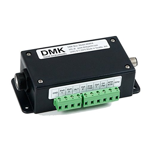
For my purposes (my engine gauges and alarms on the iPad) and low skill set I'm going to try the DMK approach first, then let a tech play if we must. This looks like a lot of functionality when you get the iPad display gratis.

41XB-Pnj8DL.jpg
 
We can definitely keep version 1.0 below $100 if that's the wish. Using serial break-out boards and having two thermocouples pretty much doubles the cost. The benefit to the serial boards is simplifying the code and reducing the number of pins used. For example, a base 16 X 2 display is less than $10, however the serial version is $25. Also, the two thermocouples adds about $50. We can re-arrange version 1.0 to keep it under $100, in this case it would have a tach and five water temp sensors, and the display would be mounted on the arduino board. But after getting into the design that seems "penny wise and pound foolish" since it would limit the expand-ability.

Ultimately I'm all for consensus on the project since the more adopters we have the stronger it will be.
 
Keeping it cheap is part of the fun but perhaps a better way to sort out the needs of the base system is number of engines supported. Folks like Northern Spy and I have single engine boats without gen set. Some members have twins with three generators. I'll step out on a limb and say that last category of user has no interest in a homegrown project. So I'll edge a bit further out on the limb and assume a user with twin engines and a single gen set will probably represent the user needing the most data points so recommend expandability stop there. Of course those with multiple engines can also use multiple independent systems as an option but that seems clunky to me.
 
I have a single engine trawler and I've been thinking there is an independant system for each - just as there are separate dashboard guages for each engine.

I think I should put together a poll to determine which features, as well as dual engine support should be included in V1.

I've never done a poll before - would somebody like to put a poll out there to help us understand which features are in most demand.

Thanks,
RR
 
DMK fits the bill of a purpose built, bolt-on marine-grade monitor. It's great solution but it's less flexible than the Arduino and doesn't really have the same "Maker" appeal (see https://en.wikipedia.org/wiki/Maker_culture. for more information

Check out all the sensors you can wire into an Arduino: SENSORS 3D Printing, Arduino, Robotics | Sainsmart. For example, they have a flame sensor for less than $5.

For some of the more advanced features, like wifi, nmea integration, integration with an iPad we might consider adding a Raspberry Pi. This provides a linux system on top of the Arduino, so you could add a web server for the iPad - or anything with a browser. You could even use a ChromeCast to view data from a flat-screen TV. This might be more like a version 4 or so.
 
For those of you who are interested in building the system please complete this anonymous survey: https://www.surveymonkey.com/r/V7DTYLG

It basically asks about what features you want and your comfort level of working on this type of project. I am using the responses to help guide the design. If this type of project is new to most people then I'll lean towards keeping it as easy as possible.

Thanks,
Robert
 
Five people completed the survey so far. Attached are the results. From looking at the results:

  • Tach, coolant temp, and water flow are the most requested sensors
  • Most people want a monitoring system, and want to make something useful while learning about Arduino
  • Everyone is comforable that the system is not to be relied upon for safety reasons
  • The majority of people are willing to spend up $300
  • Everyone has some degree of experience with electronics
  • Most people have not worked with Arduino before, but some have
  • Most people have little or no programming experience

These results indicate the following designs:
  • Spend a little more on breakout boards because it significantly simplifies the programming
  • The steps to download and install the software onto the Arduino should be well documented and easy to follow
  • The first version should have: tach, water/coolant temps, and a water flow indicator
  • Most people plan to use it while underway, so the display should have a separate enclosure mounted near the dashboard.

My next steps are to revise the design and come up with a new bill of materials. I suspect the water flow indicator is about the same cost as the two thermocouples so we are still in the $200 ball-park.

Thank you for completing the survey. If you are planning to build the system and have not yet completed the survey please do so.
 

Attachments

  • DIYMarineDieselMonitoringSystem.pdf
    255.3 KB · Views: 82
DMK fits the bill of a purpose built, bolt-on marine-grade monitor. It's great solution but it's less flexible than the Arduino and doesn't really have the same "Maker" appeal,

I cited DMK as a reference solution, production form factor and retail price - but certainly appreciate the "maker" mood that is part and parcel of it. In fact, I was thinking of installing mine with steampunk whistles for alarms.

Just cruising. Still...as the philosopher Sting said "I'll be watching you..."
 
There are four more replies to the survey and the new results are similar to the ones noted in the earlier post.

Need some advice on the water flow sensor.

Aqualarm makes nice, marine-grade water flow indicators (Cooling Water Flow : AQUALARM, Warning Systems For Land And Sea). I've seen some resellers with prices in the $60 - $70 range.

However I'm striving to keep things as non invasive as possible, and the Aqualarm product is a tube that is spliced in with a paddle indicator. I'm not wild about the design since it seems vulnerable to fouling and is expensive.

A non-invasive solution is available however it is complex and there are no reference examples with an arduino. It uses two ultrasonic transducers to detect water flow, and it can even determine the the flow rate. Knowing the flow rate is attractive because it lets us understand how our impellor is working and if the raw water system is becoming fouled. The sensors and companion chip are relatively cheap - probably around the same cost as the Aqualarm product. However this solution would be a first in the arduino world and would likely be error-prone since it's not a mature design.

I'm thinking the water flow indicator should be a version 2 feature because it's complicated, expensive and the demand is lower than tach, coolant temp, and other temp sensors.

Please let me know if there is water flow solution. I've looked at the paddle-wheel style and turbine style but I don't think they'll hold up to the environment. I'm concerned the "invasive" sensors could do more harm than good.

Currently version 1.0 is looking like:
  • Arduino stack in project box in engine room
  • Small LCD enclosure on the dashboard wired to the Arduino
  • Tachometer
  • Engine coolant sensor
  • Several temperature sensors, up to 240f, for things like raw water temp in/out, engine room temp, etc

Here are some of the options for version 2.0:
  • Raw water flow meter/detector
  • Add a communications stack for wifi, web server, NMEA, etc. This would probably be implemented with a second processor like a Raspberry PI
  • EGT
  • Oil temp
  • Boost
  • Fuel flow rate
  • Bilge water level
  • Fluid level in a tank
  • Water pressure in the raw water circuit
 
If you have inbound and outbound cooling water temperatures, you have some idea of the flow. If the inbound temp warms up, that will indicate slower water flow, and the outbound water temp will go up. So, the code can watch for a rise in inbound and outbound temp and warn of water flow loss...

Stu
 
If you have inbound and outbound cooling water temperatures, you have some idea of the flow. If the inbound temp warms up, that will indicate slower water flow, and the outbound water temp will go up. So, the code can watch for a rise in inbound and outbound temp and warn of water flow loss...

Stu

Yah, as will just an outbound temp, thus the reason for single temp sensors. Empirical measurements will define the norm and anything hotter is a problem. "Surely you know your boat"

No need for double sensors causing complexity.
 
If you have inbound and outbound cooling water temperatures, you have some idea of the flow. If the inbound temp warms up, that will indicate slower water flow, and the outbound water temp will go up. So, the code can watch for a rise in inbound and outbound temp and warn of water flow loss...

Stu

That's a good point. Some exhaust elbows have a thermocouple after the water injection. I would really like to know the flow rate though.

Based on the feedback in the survey we are able to omit the thermocouples and their break-out boards. The DS18b20 temperature probes can handle up to 257 degrees F, and they are very cheap. There are now enough pins left on the Arduino to directly control the LCD, so we don't need the serial converter. The bill of materials has gotten cheaper and is +/- $100 based on the enclosures chosen and whether you need to purchase some CAT-5 cable. I have all the components on order.

DS18b20 sensors come in many different forms. I just ordered a pack of five - each sensor is encased in a stainless probe with a 10 foot cable - for $17: http://www.amazon.com/gp/product/B00KUNKR3M

You can also just purchase the bare sensor for less than $1 each and make your own probe (Amazon.com: 5pcs Ds18b20 18b20 Thermometer Temperature Sensor: Home Improvement ). They are very small and you can drill some material out of a drain plug and epoxy one in (don't drill all the way through). You'll have three wires coming out of the sensor that should be bedded in the epoxy. I wouldn't recommend trying to get oil temp from a DS18b20 because they degrade above 257F.
 
I have "homemade" monitoring systems on both my boats. They "monitor" by sounding an auto horn at each steering station if raw water stops going into the exhaust elbow, oil pressure falls below 7, water temp rises above 200, 2nd (higher) bilge pump runs, or wet exhaust hose +250. All wired to one relay which sounds both horns. Momentary switches cancel while starting up.
My gauges will tell me where the problem is but this system will warn that there is a problem when no one is looking at the gauges which is 95% of the time. Each system has saved my butt.

The PO did something like that on my boat as well. He said if you ever hear that, look at these.
 
I have "homemade" monitoring systems on both my boats. They "monitor" by sounding an auto horn at each steering station if raw water stops going into the exhaust elbow, oil pressure falls below 7, water temp rises above 200, 2nd (higher) bilge pump runs, or wet exhaust hose +250. All wired to one relay which sounds both horns. Momentary switches cancel while starting up.
My gauges will tell me where the problem is but this system will warn that there is a problem when no one is looking at the gauges which is 95% of the time. Each system has saved my butt.

Alarms are definately in scope but increase the programming complexity. I think once we have the basics of cooling temperatures and tachometer we can venture into alarms. It probably makes sense to include a red LED and a buzzer in the on-dash enclosure.

While searching for flow meters I came across this little gem. It senses diesel and gasoline flow and is only $12.90. Scroll down to "2.0 to 30.0 L/hr Diesel and Gasoline Flow Sensor" about halfway down the page at Flow Sensor. With RPM and a fuel flow meter you could dial-in that efficiency sweet spot. I think the typical older-style diesel would need two flow gauages: one to measure the rate coming from the tank and other measuring the return rate.

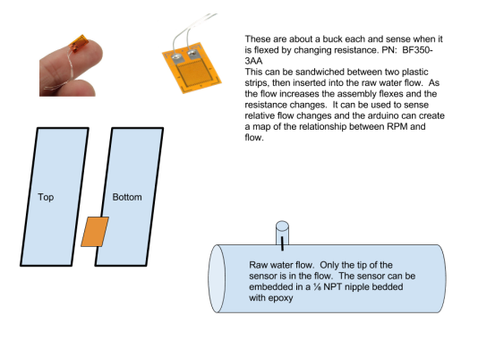
While the components are being delivered I'm working on a design for pipe that would be spliced into the raw water line just before injection to the elbow. The pipe would have a flow meter/detector and a temp sensor. The pipe would be about 6" long and have barbed fittings on each end so you could splice it in easily. The pipe would also be oversize, so if your raw water circuit using 1" ID plumbing this would be 1.5" ID, with a reducer at each end. I'm thinking a piece of schedule 40 bronze pipe or something with a wall thickness that is large enough to drill/tap NPT threads into it. A DS18B20 sensor would be embedded somehow in the pipe along with some way to measure flow. The flow measurement might just be relative instead of actually know the GPH rate. A strain gauge and a small tab sticking into the flow would give an indication of the rate.

For the pipe, what are the acceptable marine-grade materials? If there was a glass-reinforced plastic with 1/4" thick wall that would be perfect. I've heard there different flavors of copper and only some types are suitable due to work hardening.

Thanks,
RR
 
I ordered one of their water flow totalizers maybe a year or two ago. Seemed like a good way to keep up with water consumption. After a couple of months I cancelled the order and got a refund. No response on why the unit never shipped.
 
Alarms are definately in scope but increase the programming complexity. I think once we have the basics of cooling temperatures and tachometer we can venture into alarms. It probably makes sense to include a red LED and a buzzer in the on-dash enclosure.

While searching for flow meters I came across this little gem. It senses diesel and gasoline flow and is only $12.90. Scroll down to "2.0 to 30.0 L/hr Diesel and Gasoline Flow Sensor" about halfway down the page at Flow Sensor. With RPM and a fuel flow meter you could dial-in that efficiency sweet spot. I think the typical older-style diesel would need two flow gauages: one to measure the rate coming from the tank and other measuring the return rate.

While the components are being delivered I'm working on a design for pipe that would be spliced into the raw water line just before injection to the elbow. The pipe would have a flow meter/detector and a temp sensor. The pipe would be about 6" long and have barbed fittings on each end so you could splice it in easily. The pipe would also be oversize, so if your raw water circuit using 1" ID plumbing this would be 1.5" ID, with a reducer at each end. I'm thinking a piece of schedule 40 bronze pipe or something with a wall thickness that is large enough to drill/tap NPT threads into it. A DS18B20 sensor would be embedded somehow in the pipe along with some way to measure flow. The flow measurement might just be relative instead of actually know the GPH rate. A strain gauge and a small tab sticking into the flow would give an indication of the rate.

For the pipe, what are the acceptable marine-grade materials? If there was a glass-reinforced plastic with 1/4" thick wall that would be perfect. I've heard there different flavors of copper and only some types are suitable due to work hardening.

Thanks,
RR

I would use a bronze fitting if it has contact to sea water. You can probably find one that is a double ended hose barb close nipple. I don't think you'll need to penetrate the pipe unless you want to add the flow sensor. In most cases, you can clamp a thermometer sensor to the injection port and get a good temp reading. If you lose water flow, that will be a quick hot spot.

Stu
 
Bronze it is.

Attached is a diagram of flow meter that I've been considering. The sensor changes resistance as the flow rate increases. I doubt you could determine GPH, but it would you tell you if the flow rate is lower than normal. This could also have the temp sensor onboard.
 

Attachments

  • Raw water flow sensor.png
    Raw water flow sensor.png
    115.2 KB · Views: 124
Back
Top Bottom