DIY engine monitoring system

The friendliest place on the web for anyone who enjoys boating.
If you have answers, please help by responding to the unanswered posts.

R_p_ryan

Senior Member
Joined
Dec 11, 2014
Messages
171
Location
USA
Vessel Name
Shellbourne
Vessel Make
1978 Mainship 34 Perkins T6.354
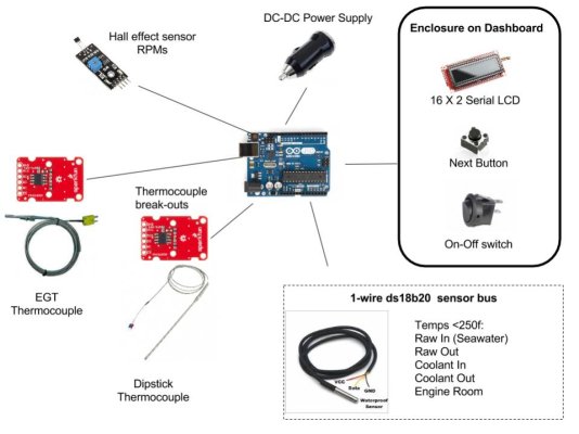
Is anyone interested in a DIY engine monitoring system based on the Arduino board? They're cheap and I can program them. Basically I'm thinking of having a board, a simple LCD display and a "next" button.

There would be set of sensors, such as tach, oil temp, water temp, boost, EGT, that you would need to install. Could even add things like raw water inlet temp, raw water oulet temp, etc...

I'd be happy to do the open-source programming and publish the schematics.

Boost and EGT are based on 1/4" npt sensor that needs to be drilled, tapped. Tach requires a bracket and 2 tiny magnets added to each side of the flywheel. Oil and water temps would have a few options, some as simple as using JB-Weld to bond the sensors to the hot and cold sides of the oil cooler. In those cases the values would be more for comparison and getting a baseline since they would not be accurate.

Total price for the board and a few sensors would be less than $100 and you'd get it all from Amazon.

Base board:
http://www.amazon.com/arduino-org-A...e=UTF8&qid=1450373441&sr=8-2&keywords=arduino

Temp sensors (5 for $12):
http://www.amazon.com/Vktech-DS18b2...78&sr=8-1&keywords=arduino+temperature+sensor

Tach sensor:
http://www.amazon.com/SainSmart-Eff...73556&sr=8-1&keywords=arduino+magnetic+sensor

EGT Sensor:
http://www.amazon.com/SainSmart-MAX...50373612&sr=8-1&keywords=arduino+thermocouple
 
I'm interested because I love to see as much engine data as possible. I don't have turbos, but would like to see things like EGT, water flow, volts, amps, oil temp, trans temp, etc.

Ken
 
I imagine the thermocouple could be used for coolant or whatever temp by threading into the appropriate passage. Or are treaded sensors available?
I don't like attaching to the outside unless there are no other options.
 
I imagine the thermocouple could be used for coolant or whatever temp by threading into the appropriate passage. Or are treaded sensors available?
I don't like attaching to the outside unless there are no other options.

Basically there are two types of temperature sensors. The typical is the thermocouple, which uses the change in resistance to determine the temperature. The newer style uses an embedded silicon sensor. The newer style is very accurate and the reading is digital. The thermocouple reading is analog, and there is an added converter to digitize it. Thermocouples have a higher amount of variance however they can tolerate extremely high temperatures. The digital sensors are actually cheaper since they don't need a converter but can't tolerate more than about 240 degrees F.

It would be nice if there was a way to introduce a sensor underneath a hose at the hose clamp. This way you could easily add several temp sensors throughout the raw and fresh water circuits without having to drill/tap to get accurate readings. My guess is only the thermocouple style would work in that situation, and have like a flat ribbon cable so the hose wouldn't leak.
 
As this would be useful beyond boating I'd love to see open source design schematics.
 
Is anyone interested in a DIY engine monitoring system based on the Arduino board?

Total price for the board and a few sensors would be less than $100 and you'd get it all from Amazon.

I'd be interested. Inexpensive enough, and sounds like fun.
 
I'm kind of concerned about your comment that thermocouples change resistance with changes in temperature. Did you mean RTDs?
 
Engine data

I would be interested
 
I'm in. I used a Noland that recently failed (board issue) so always wanted to replace it. This would not be networked, but then I only have one helm now so don't need a networked device.

Tom
 
I'm kind of concerned about your comment that thermocouples change resistance with changes in temperature. Did you mean RTDs?

Yes, he did. RTDs use resistance, TCs use voltage. But I'll excuse that...

I'm in. I've been putting off a monitoring toy like this for awhile. The flip side is, the longer I put it off the more resources there are and less expensive it will be.
 
An arduino board wont have inputs suitable for the various sensors. Its not impossible to design custom inputs that are compatible, just a pain sometimes.
 
The thermocouple I posted includes the converter board, so it should play well with an Arduino.

Regarding the resistance/voltage on a k-type thermocouple you are both correct! I respect the analog world, but I grew up digital.

Nice link to the hose coupling with the thermocouple adapter. That would fit nicely on my raw water side, but the FW side is 2". I don't mind tapping the steel pipe or brazing on a threaded fitting.

I looked around and didn't see any similar projects. I'd host it on GitHub, and probably start by using design for the tach: Arduino RPM Counter / Tachometer

I dunno if any of you are programmers and would be interested in contributing? With GitHub we can have as many people as we want to help out. Arduino uses a C style language and the IDE is free to download.
 
My apologies, I didnt take the time to look at all the info you provided. The serial interface is easy to hook up, so you should have little trouble. Well relatively little trouble, you know how new endeavors can go... :)
 
I put together some thoughts on how to start up this kind of project. I put together a rough draft charter and would appreciate feedback on it if you are interested in either developing the kit or just interested in providing insights on ways to make it better.

I couldn't think of a cool name the system "Open Source Marine Monitoring System, "OSSMS", or something along the lines of monitoring or knowledge. I thought of "Eye of Sauron", "Owl", and "Oracle". I'm hoping somebody can find a better name.

Below is the charter.
Thanks,
RR

Oracle (or whatever we choose to name it)

Purpose: Build an Open Source DIY marine engine monitoring platform kit based on the Arduino Uno with a virtual team from Trawler Forum

Objectives
Publish the specifications, code, instructions and a bill-of-materials for the Maker to perform the build.
Skills needed to build the kit are limited to simple soldering and troubleshooting with a multi-tester
Design the platform so it can eventually handle any type of Arduino-tested sensor, display, or sound.
Keep the project cheap, fun, and easily to customize.
Keep the builders informed with design inputs from the Trawler forum
Architect the UNO in such a way so new feature may be added
Allow each builder to specify which sensors, switches, and LCD screen they want
Let the group grow so new people could contribute new features.

Approach
Use an Agile, iterative style to release a simplified version first and then continue to iterate and deploy more sensors and features. For Example, the exact versions and features are voted on by the whole team to change the priority
- Version 1.0 might only have a digital tachometer and a screen. Turn it on and the RPMs are shown
- Version 1.2 might add on four water temp sensors and a button to toggle through the data on the screen
- Version 1.3 might add on a pyrometer
- Version 1.4 might have boost
- Version 1.5 might have hot-oil and cold-oil readings from before and after the heat exchanger.
As we develop more features we can choose which ones to publish to the kit. For example we might not publish the kit until we’ve developed 1.3 and ran it for a few months

Team: Anybody who is willing to help is welcome. You don’t need to know programming or electronics to help.
For example, we need somebody to represent the user’s perspective with a fully installed system. He/she could help us design the “Look and Feel” of it, and the best way to present engine data. We would send you the pictures of the screen with engine data on it, plus a description of a button and how you would scroll through the different sensors. You would provide feedback on how appealing it is, and suggges===
Programmers: If you have ever done any C style programming then you can easily work on Arduino. The IDE is clean with sample code.
Electronics specialists/engineers: If you are familiar with the basics - like a pull-down resistor or how to debounce a switch then you would be helpful on the project
Diesel specialists / mechanics: You have information on where best to locate sensors around an engine to get the best measurements. Your feedback would be very helpful.

Thanks,
Robert
 
If I can ask guys why build specialized hardware, and specialized code.

Today, off the shelf you could buy a PLC and a display, program it, and have a "digital gauge package" to work with legacy engines.

There might even be a already programmed solution off the shelf.

Yes, it sounds interesting but workable solutions already exist, why reinvent the wheel?

I'll guarantee that if a HMI engine and even whole boat monitioring system were what a process control professional was after they could buy the off the shelf parts today and have a working unit very quickly.

Stat your search at places like automationdirect

I've worked in the SCADA and networking world for a lifetime, and although I do not want to put so many eggs in a single package, it would be relatively easy to do.
 
Last edited:
I've done sat control systems and such but on a boat, we already have several networks. Why not use NMEA 0183 or N2K to make it compatible with what others might already have.

What about SignalK?

I know maretron has tons of sensors designed for marine applications but their price is probably higher for one sensor than for the whole monitoring kit with an Arduino.

One thing I would make sure to check is opto isolation to remote sensors, and power management for the arduino. I would put a DC-DC converter on the arduino board, since starting an engine can put some amazing power spikes on the source. I would do this regardless of whether it is powered by starting batteries or house batteries. You might want to parallel two 18650 batteries on the arduino side to give you a few hours of battery backup.

I would support a wifi shield so you could use a tablet or phone as a remote display.

Stu
 
After following Twisted Tree's blog outfitting his new Nordy I believe I'd run not walk away from anything to do with N2K network interface.
 
If you use RTD or NTC Sensors

You need to specify a sensor wire type. Some PLC use twisted pair some use shielded wire. Cannot be run along or near HV AC >24VAC. etc etc.

In the perfect (industrial) world 4-20 MA sensors are used. As long as you have 20 MA in your circuit you can have a two mile long sensing circuit.

The thermocouple I posted includes the converter board, so it should play well with an Arduino.

Regarding the resistance/voltage on a k-type thermocouple you are both correct! I respect the analog world, but I grew up digital.

Nice link to the hose coupling with the thermocouple adapter. That would fit nicely on my raw water side, but the FW side is 2". I don't mind tapping the steel pipe or brazing on a threaded fitting.

I looked around and didn't see any similar projects. I'd host it on GitHub, and probably start by using design for the tach: Arduino RPM Counter / Tachometer

I dunno if any of you are programmers and would be interested in contributing? With GitHub we can have as many people as we want to help out. Arduino uses a C style language and the IDE is free to download.
 
These are great ideas.
The ScanGuage display is similar to what I was thinking. A compact unit with a button to display the next sensor's output. Thanks for the link to it, the user-interface provides some guidance.

The PLC route is definitely something to consider. I've used a PLC before but found it more difficult to program than an Arduino. The device could be SignalK-compliant, and provide a JSON endpoint to return engine statistics. And putting it on wifi is also a great idea since it could send me a text message when my bilge switch turns on. I'm thinking an Agile approach makes sense, and we can focus on small iterations.

The vastness and cheapness of the Arduino platform is appealing, as is the open-source nature of it. With all the shields available there is an unlimited degree of flexibility. I think Waspmote is pretty interesting too.

Regarding reinventing the wheel, we should disclaim this project is for the maker / do-it-yourself type and the system is not to be depended on when safety is at stake. If you're looking for a proven, purpose-built, marine-grade, bolt-on device then this isn't it. This is for the person who enjoys creating things, is on a budget, and wants more information from his/her engine.

Stubones99:
Thanks for the information. I agree with the DC-DC converter. You bring up a good point with the opto-isolation. I've been assuming this is for a marine diesel, so there wouldn't be the EMF of a gasoline ignition. Can you explain the need for opto-isolation? I don't know how we would be able to provide opto-isolation of the arduino from the sensors. Each sensor will have a pull-down resistor that should help dissipate stray energy. Currently I have the Arduino connected to my EGT using a simple K-type thermocouple with a small converter board and haven't had any issues. I'm playing with the magnets and the sensor for the tach - I could imagine getting stray energy from the alternator. Can you please explain more about the opto-isolation?

The first iteration:
What do people think about oil temp, tachometer, and EGT as the first three sensors? I'm thinking the Arduino would be mounted in a case on the bulkhead in the engine room, with a compact display/button similar to what_barnacles suggested in the ScanGuage design. The display/button would be connected to the Arduino using a CAT-5 cable. The display could be something like a 16X2 in a small enclosure.

Thanks,
Robert
 
This would be the layout of Version 1.0. The basic architecture is to off-load processing to break-out boards. The break out boards do the work and can be queried from Uno. This reduces coding and complexity. This frees up pins and simplifies the construction and cost. Materials cost less than $100, but that doesn't include wire, solder, enclosures, etc.
Features:
  • Compact, dash-mounted display
  • Digital RPMs
  • Oil Temperature
  • Exhaust gas temperature
  • Raw water in
  • Raw water out
  • Engine coolant leaving engine
  • Engine coolant leaving heat exchanger
  • Engine room temperature

It supports:
  • serial display board with 2 lines of 16 characters
  • Next button
  • Thermocouple break-out boards for EGT and Oil temp
  • 1-wire bus for several temperature sensors, max temp 250F
  • Basic USB car charger for power supply

Please let me know if the is correct feature set for V1. I would like V1 to be successful and reliable; not complex and abandoned.

Assuming we have agreement on the V1 feature set I'll search for display enclosures

I think version 2.0 would create some intelligence, such as a red light or buzzer when a value exceeds normal.

From looking at all the low-cost add-ons I'm wondering if the UNO is going to have enough pins to support the future. It would be easy enough to upgrade to a Mega if neccesary and have wasted too much time on trying to "future proof" this.
 

Attachments

  • Version 1.0.jpg
    Version 1.0.jpg
    66.6 KB · Views: 137
The opto-isolation will prevent any accidental 'let the smoke out' events when power from another source gets into a sensor wire.

Wiring should be high temperature (insulation) since any accidental contact with exhaust manifolds, etc. could result in shorts which could smoke the D/A shield.

When you say raw water in and out, I assume temp and not water flow?

you also may want to consider a temp sensor on the shaft seal (packing temp).

Also, a temp sensor for engine room? fire sensor?

And you may want to make the provision available for twin engines (two arduino)

plan on being able to log data points to be able to create a "normal" for each sensor. That way, you can quickly see a rising / falling trend and sudden out of normal data ranges.

I will see if I can get the code for an old compiler / macro language I wrote many years ago. I think I could adapt it to be able to do ad-hoc coding.

What OS will the Arduino be running? What dev kit would you start with?

My son in law is an arduino & android developer (current) and I'm ancient developer from DOS, OS/2, Windows, and a bit of IOS development lately. i think this would be a fun project and would enjoy tinkering with it.

While I don't have a boat and can't get out on one now (medical) my brain wanders aboard almost daily :)

STu
 
You need to specify a sensor wire type. Some PLC use twisted pair some use shielded wire. Cannot be run along or near HV AC >24VAC. etc etc.

In the perfect (industrial) world 4-20 MA sensors are used. As long as you have 20 MA in your circuit you can have a two mile long sensing circuit.

BigJim,
Thanks for the info. I know very little about RTDs. Currently I have a low-cost, stainless steel encased Type-K thermocouple for the exhaust. Do you think I should use an RTD instead? I am planning on having the Ardiuno on a bulkhead in the engine room so the wire lengths would not exceed 8 feet.

For sensors that are never exposed to 250F I was planning on using the electronic "one-wire" protocol with digital ds18b20 sensors

This raises a good discussion on temperature sensors:
Thermocouple vs RTD vs ds18b20

I am no expert on this and these are thoughts about the different temp sensors
  • I don't know enough about RTDs to comment
  • Thermocouples tolerate extreme heat and require a break out board
  • DS18B20 is very accurate and low cost. A single pin can be used to query many sensors

Please let me know if I've gotten any this wrong, and please let me know if the RTD should be included.

Thank,
Robert
 
maretron has a switch closure sensor for water flow. it is a plastic housing and should work to report if water flow drops below a set point. I think it is a paddle / spring thing where waterflow has to get to a point to push the paddle down.

How many current loop circuits does the shield support?

Are there digital loops available? If so, how many?
 
twisted pair shielded for the temp sensors should be fine. diesels really arent that noisy electrically. with the rtd's you are back to what I said originally, needing to design interface circuits.
 

Latest posts

Back
Top Bottom