Delfin wrote:
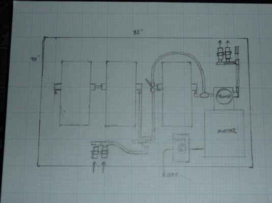
If you're not going to polish fuel while the engine is running, then there isn't an issue.* I am assuming that the two Racors on the left are the secondary filters supplying fuel to the injector pump.* If so, you don't want the injector pump to be working against the polishing pump but if you don't run them at the same time that's not a worry.* My suggestion to take off the injector pump supply from the output side of the Procon also assumes that the Procon will pass the required flow whether it was running or not, which as I think about it, may not be the case.* A day tank would solve all of this.
Incidentally, if you have to mount the motor with the pump above, it's not the end of the world, it's just a best practice so that if a pump leaks, it doesn't leak into the motor.