Balancing house batteries

The friendliest place on the web for anyone who enjoys boating.
If you have answers, please help by responding to the unanswered posts.
Joined
May 24, 2015
Messages
1,135
Location
USA
In the short haul refit thread the following like was provided for some guidance in balancing batteries for power draw. SmartGauge Electronics - Interconnecting multiple batteries to form one larger bank

I dont see where the author determined that the batteries in method 2 are out of balance. I'm hoping someone can point out to me where I am missing the imbalance.
Starting from the bottom and counting "short links" for each battery to get out of the bank I see...

Pos. side, Neg. side, Total
0 3 3
1 2 3
2 1 3
3 0 3

Since the current path for each battery is from the neg. terminal thru the load and back to the pos. terminal, all batteries see the same number of "short links" so the current draw should be equal for all 4 batteries.

Right?

Method 2 reposted for the sake of discussion...
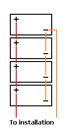
batt_new.gif
 
IMO various schemes that are proposed to balance multiple batteries wired together are splitting hairs. Wire them any way that makes you feel good. They are all the same at the end of the day.

David
 
IMO various schemes that are proposed to balance multiple batteries wired together are splitting hairs. Wire them any way that makes you feel good. They are all the same at the end of the day.

David

:thumb::thumb:
 
Jeez do I need to start a blow boats are better thread to get a discussion?

LOL

You're not being ignored. I'm stuck at home doing renovations...most others are probably out on their boats :socool:
 
Okay ... Let's start some thread drift ...


Can we expect a series of house batteries to wear out evenly given the same age?
 
In the short haul refit thread the following like was provided for some guidance in balancing batteries for power draw. SmartGauge Electronics - Interconnecting multiple batteries to form one larger bank

I dont see where the author determined that the batteries in method 2 are out of balance. I'm hoping someone can point out to me where I am missing the imbalance.
Starting from the bottom and counting "short links" for each battery to get out of the bank I see...

Pos. side, Neg. side, Total
0 3 3
1 2 3
2 1 3
3 0 3

Since the current path for each battery is from the neg. terminal thru the load and back to the pos. terminal, all batteries see the same number of "short links" so the current draw should be equal for all 4 batteries.

Right?

Method 2 reposted for the sake of discussion...
batt_new.gif
I suspect that it's to do with the fact that the batteries aren't symmetrically placed in the circuit. It's not just the total number of the short links, it's where they are in the circuit. If you think about the potential across each battery it's not going to be the same with the potential drops across each short link. That's what I think is creating the imbalance.

As to the significance of this - if you believe the author's calculations, there are big differences in battery draw (especially going from #1 to #2). I suppose that will affect battery life?

Richard
 
I really wish the author of the Smartgauge piece would prove it in practice as well as theoretically. It would be a bit of work, but given the enormous number of hours that we, well you, spend reading this stuff it would pay out.

Hook up 4 new batteries as in method #1. Charge them up completely. Check with a SG meter to make sure. Then draw 100 amp hours from them until they should be 50% discharged. Then measure the SG of each battery to determine if the one on the top end is only 25% discharged as his calculations predict.

Want to bet on the outcome?

What is wrong with his calculations? Mostly that internal resistance of a battery is not a constant, it varies with current, more resistance for higher current draws which will tend to balance them out when wired as in method #1. And I have no way of knowing whether his assumed .02 ohms of constant internal resistance is reasonable. I doubt it, particularly for AGMs.

David
 
I think a buss bar adjacent to the battery bank with uniform cable length from each battery to the bar handles it best. Then, between the buss bar and main panel feed before anything else have a fail safe disconnect that shuts down everything. Allows greater flexiblity. Problem battery could be pulled out without upsetting the rest. If one starts smoking, steaming or otherwise behaving badly take it off the buss but leave the rest.


In the short haul refit thread the following like was provided for some guidance in balancing batteries for power draw. SmartGauge Electronics - Interconnecting multiple batteries to form one larger bank


I dont see where the author determined that the batteries in method 2 are out of balance. I'm hoping someone can point out to me where I am missing the imbalance.
Starting from the bottom and counting "short links" for each battery to get out of the bank I see...

Pos. side, Neg. side, Total
0 3 3
1 2 3
2 1 3
3 0 3

Since the current path for each battery is from the neg. terminal thru the load and back to the pos. terminal, all batteries see the same number of "short links" so the current draw should be equal for all 4 batteries.

Right?

Method 2 reposted for the sake of discussion...
batt_new.gif
 
"Can we expect a series of house batteries to wear out evenly given the same age?"

NO,, the usual practice is to rotate the first batt to the back of the string every year or so when the terminals and wiring are cleaned.

Less necessary if you have/use a good desulfation device.
 
I suspect the potential benefits of a particular battery wiring likely depends on the loads on the bank. Big inverter loads probably cause greater imbalance to the individual battery voltages on a bank than small DC loads such as fridges. Just my guess. We just rewired our AC panel so the microwave is on the inverter side of the panel and it draws 130 amps at ~12.5 volts for the 3 minutes it's on. The fall project is to re-cable our house bank to optimize the loads across the batteries.


Jim
Sent from my iPad using Trawler Forum
 
once you hook two or more batteries in parallel the best will charge the weakest and supply more load than the weakest.


Not unlike a large hose and a small diameter hose in parallel. At rest the pressure will be equal but at heavy flow the little hose will supply less water.


There is no way around that.
 
Last edited:
what b...

The author admits #2 is close but goes on to explain his reasoning...

"In the 2nd example (the much improved one), the power from the top and bottom battery both passed through a total of 3 links. That from the middle 2 batteries also both passed through 3 links which begs the question "why were they not therefore perfectly balanced?". The answer is that some of the links have to pass more total current and this therefore increases the voltage drop along their length."

That's the theory but you can see from his calcs that the difference is small in this case. My take on it that by using #2 vs #1 you are a lot closer to ideal with a relatively simple mod'n.:thumb:
Some will argue does it make a difference?
My feeling is why wouldn't you do it it so simple?

and... there are other things to argue about like which anchor are you using while running off the house batt'ys and wondering or calculating if they will last:ermm:
 
Ahh I must have missed his reasoning Bacchus. Thanks for pointing it out.

I'll have to ponder that some.
 
Method 2 has always been the generally accepted best practice for a parallel bank. And, hook the battery charger up the opposite way from the loads: the upper left hand + in the picture above and the lower right hand -. Helps isolate the loads from any voltage spikes or noise from the charger.
 
And, hook the battery charger up the opposite way from the loads: the upper left hand + in the picture above and the lower right hand -. Helps isolate the loads from any voltage spikes or noise from the charger.

cal...

Not so according to SmartGauge... they say...

"And finally, finally, we keep getting asked where the chargers should be connected to. We didn't address this question because it seemed so blatantly obvious where they should be connected that it never occurred to us that anyone might be unsure.
The chargers should always be connected to the same points as the loads. Without exception. "

They don't include the rationale and it wasn't that obvious to me!
 
Method 2 has always been the generally accepted best practice for a parallel bank. And, hook the battery charger up the opposite way from the loads: the upper left hand + in the picture above and the lower right hand -. Helps isolate the loads from any voltage spikes or noise from the charger.

Ok, but what is the suggested method when you have alternators charging and an AC charger and where do you take the load from?
 
I have a hard time believing what he is saying. I would like to see a 100 amp load applied and each link tested with an amp meter. The links are too short to cause any measurable voltage drop if the cables are sized correctly and the connections are tight. I think this might be a case of one thinking too much. It has been awhile since I have done any voltage drop calculations but the cable length is so short it would be futile anyway. I think the only way you could have the different amp draw that he claims in methow 1 is that the batteries are not in the same state of charge. Thus one is maybe 12.6 volts and another maybe 12.2. If that is the case the amperage draw will be different no matter which wiring method is employeed.
 
Back
Top Bottom