Wiring IsoProCharge

The friendliest place on the web for anyone who enjoys boating.
If you have answers, please help by responding to the unanswered posts.

Bohans

Veteran Member
Joined
Jul 25, 2011
Messages
82
Location
Australia
Vessel Name
Ohana
Vessel Make
DeFever 72
Hi Everyone

Was hoping for help and clarification on wiring the IsoProCharge unit into my boat.

I am looking for the simplest set up possible.

What I have is this...

2 x Main Engines (Cummins NT855)
1x 12 v 160amp alt. connected to Stb motor (port motor has 24v alt to charge a completely separate inverter bank which is not part of this equation)
1 x Engine start bank of two 8D batts. 12v
1 x House Bank of 800amps 12v.
2 x Gensets with alts both 12v.

What I want to do is this...

1. Wire the Engine start bank to start both the main engines and the gensets. I would do this via two separate battery switches, 1-2-both.
2. Use the House Bank to emergency combine with the Engine Bank via the switches mentioned above.
3. Charge the Engine Bank and House Bank with the IsoProCharge.
4. Run the Genset Alts directly back to the Genset starter to go back to the Engine Start Banks.

I have two separate 12v main electricity chargers to charge the house and engine banks separately.

Can anyone mock up a diagram for this arrangement please...I have put a rough diagram together but am a little confused where to join the Negative cables either to each engine and link together or keep separate.

Thanks for any assistance.

Bo
 
Ok, I don't know the IsoProCharge unit and googling it brought me right back here.

Do you have a link that offers a description and a mfgr. manual online.

As for the negatives, verbally, the negatives should all go back to ONE buss bar that the batteries are also connected to. One neg from each engine to the buss bar.


But as for specifics the link might help.
 
Thanks for that.

I was going to send all the Negative to their respective spot on the starter motors then bridge both engines together with cable to join the negatives. Just not sure if I need to do this. For the two main engines how else are they "linked" together through their Earth/negative connections.

http://promariner.com/wp-content/uploads/2013/05/PROISOCHARGE-MANUAL-REV-VIEW.pdf

Manual above.

Thanks

Bo
 
Depends upon the starter motors. Your engine may have an ISOLATED starter meaning the starter actually has it own neg connection. Often a lighter neg. wire is then run from the starter negative to a bolt on the engine block close by to pick up the alternator and any alarms/sensors neg.

Many starters ground through their own case to the engine block. Then the eng. block must have a negative run back to the batteries/buss heavy enough to take the starter current.

In either case it is NOT a good idea to jumper between the engines. Each eng. neg. should go back individually to the batteries/buss.

Although in many cases this would be OK and not cause trouble it can cause trouble with circulating currents. Avoid that trouble. Just be sure the main neg. wire, whether from the starter directly or from the engine block, is in top notch condition and goes back to the buss.

if you do not have a buss for the negatives at the batteries and you have a mess of connections at the batteries then that should be cleaned up using a buss.
 
Yes you are spot on in that my starter motors both have their own Negative terminal on them. So this is isolated from the motors ground connection then?

I shall run the cables as they currently are with the negative from engine starters back to the battery negative terminal. Do this on both motors and should be fine.

Thanks

Bo
 
So this is isolated from the motors ground connection then? Yes, the neg. terminal is isolated. If you look closely there may be another short jumper to the engine block to pick up the other functions. The engine block ground could be elsewhere also.


I shall run the cables as they currently are with the negative from engine starters back to the battery negative terminal. Do this on both motors and should be fine. Yes
 
Just another quick question...

Given a choice, would you attach the mains chargers to the battery switch terminal or directly to the battery bank positive. Which is going to give most efficient charging or does it not matter.

Also, I found that my Engine starter negative terminal goes to the negative terminal on the alternator. this then goes via a cable to the generator engine case...

Thanks

Bo
 
Fryedaze (Dave) has installed the Promariner dc charging system on his boat. I suggest you send him a private message.
 
Last edited:
Call the techs at ProMariner. They may ask for a drawing from you to get an idea of your needs.

They set me up with this. 2 engine inputs and 4 outputs. It wasn't hard to install, but I spent more on wire than I did for the unit.

DSCN0444.JPG
 
Call the techs at ProMariner. They may ask for a drawing from you to get an idea of your needs.

They set me up with this. 2 engine inputs and 4 outputs. It wasn't hard to install, but I spent more on wire than I did for the unit.

DSCN0444.JPG


How's the installation working for you?
 
How's the installation working for you?

Great! The unit senses and if needed sets the start batteries as a priority. Then switches over to the house batteries. The unit is all electronic with no diodes so you don't have the issues you had with the older battery isolators.
My install makes it easy to see on the back bulkhead of the ER. No compliants...
 
Also, I found that my Engine starter negative terminal goes to the negative terminal on the alternator. this then goes via a cable to the generator engine case...
-----------------------------------------------------------------------

Hmm, without actually seeing all the system and arrangement this sound not quite right.
It obviously works or worked or you would not now be able to start.

I could see using the neg main engine starter lug as the ground from the alternator which actually is approx the same as I suggested before about an engine block neg. bolted on near to the starter to pickup the engine block , sensers, alternator. They have simply chosen the alternator as the engine block neg. point and picked up the alternator also.

The run to the gen. may have been done that way to save wire [not duplicate] especially if the gen is between the engines and the batts. picking up the gen in the process.
Strictly speaking there is probably nothing wrong but personally it does not sound like the best but as long as the connections are maintained, the wire is in good condition and it works then carry on.

This may be one of those situations where a pair of experienced eyes need to have a look.
 
Thanks for the replies. I appreciate them.

I have started pulling and labeling all current wires to all associated motors -4 in total...

My aim is to create a larger house bank and separate start bank. I current have separate house, mains start, two genset starts...4 banks and 5 battery switches. Too much...

by the time I finish I shall have an on off for the house switch a large house bank and separate start bank for all engines with an ability to combine in with the house if required in emergency. There will be three battery switches only.

both banks are charged from one alternator on the main and when either genset is running its alt will charge the engine bank also. The Iso Charge unit splits to both house and engine start banks.

I am reconnecting all negative wires and redoing all the terminals.

shall see how it goes.

thanks

Bo
 
Bo,

make sure to keep us up on your progress and post pics.....
 
After about 8 hours of pulling cables and marking them, then redesigning the system without the isoprocharge it has all come to an end...the two big main engines did not like the idea of longer cable runs especially the port motor. I should have known...anyway, I have now put it back to the way it was. My boat has split engine rooms and the cable runs are too long with a start bank on one side. Now my start bank is in the middle exactly between both motors. All fine now. But back to all those switches.

I have put the isocharge in and am waiting to install the alternator wire as I have to extend that cable with a terminal join.

shall put photo up when done.

Bo
 
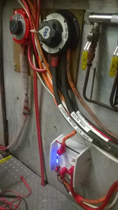
Finished wiring and testing my new Pro ISO Charge unit.

I refreshed all wiring and connections, made sense of how it all works.

Here are some photos.
 

Attachments

  • Iso Pro 2.jpg
    Iso Pro 2.jpg
    97.8 KB · Views: 91
  • Iso Pro 1.jpg
    Iso Pro 1.jpg
    103.7 KB · Views: 77
THanks for the comment. I appreciate it.

Next job is to install two Engine Room cameras.

I have bought two foscam HD cameras and they wirelessly send images to my laptop or phone. I am putting them in today all going well.

Shall post a pic when done.

The engine rooms currently have a wired Raymarine camera in each room, but this is such poor quality compared to the new Foscams...Raymarine are also about 6 times the price. They must have lost a lot of market share to these non-marine companies.
 
Where did you get them? Do you need to run your ER lights for the camera?
 
THe cameras I purchased direct from Foscam. BUT I had to buy the wireless router and I set it all up in my office and it worked fine.

Then I took it to the boat and the router essentially will not connect to the cameras nor the laptop reliably. There seems to be too much interference on the boat from other radio signals...So I will hard wire the cameras through to the pilot house and set up a new router up there.

The boat is about 70ft long and a flush deck motor cruiser so it is fairly big and the signal just may not travel well in this environment. I shall see when I set it up differently.

Also, if there metal between the wireless devices, the signal is weakened big time. Many wireless devices are still wireless N which doesn't have the greatest range to start with. My PC marginally connects to our Airport Extreme router at 50-60 feet but there is some concrete obstructions.
 

Latest posts

Back
Top Bottom