Sailor of Fortune
Guru
Lots of work but I agree with teakless deck. I'll second the KIWI grip scenario on that deck.
Specs for the Cherubini 45'
LOA 45'
LWL 42'
Beam 14' 6"
Draft 4' 6"
Displacement 32K to 36K depending on the source.
Ted


 Outside is much worse. It's winter now and the building is closed up. Everything is covered in dust. It resembles a fresh dirty snow fall.


Holy crap! Does Sean have a wife and kids that I can kidnap and get him to do work on my boat?
Ted, when do you think you will be back in the water? If I am out this spring I may hit Somers Cove.
Larry, don't know if you missed that part about duck hunter. He has more guns than Manyboats has anchors. Sean is very conservative and protective of his family (wife, 2 kids and dog). I imagine he would hunt you down and field dress (gut) you so that you would remember not to do it again, before he killed you. Intentionally hurting his dog (Roxie) would probably be a fatal mistake.
Ted
I think Bucky is already purdy. She may not be everybodys' cup of tea, but she looks to fulfill her mission statement/design admirably!!From what I can tell he likes money. Probably could even make Bucky looky purdy.
Ted


 There is a brace that runs from underneath the high section down to the transmission mount to help support the weight. Below the discharge will be a 12" x 12" x 12" lift muffler. The discharge will go straight up then straight back over the genset before turning to starboard then out the transom. All the remaining exhaust parts are waiting for me to return from FL in a couple of weeks to install them.

 As space was limited in the engine room, the four 8D battery boxes were mounted next to the engine making it really tough to do engine maintenance.


 From left to right. Positive power distribution panel. There is a house bank battery switch and the engine emergency start switch. Engine battery is next to the engine with 16" battery leads; no point running extra wire and another switch. The emergency switch allows the engine to be started off the house battery. Next is the always on fuse panel. Above it is the shunt for the Victron Battery monitor.


Really nice attention to detail, should make for a very reliable and sound vessel. Any thoughts on sound deadening as well as what is your cruising plans with this fine new vessel?
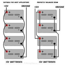
Your house bank is just like the one I am currently working on! (without the perfectly made custom box)....
You may want consider this connection set up for where you come off the bank.
Boat was well sound insulated with soundown insulation. Have added some more in areas, but will do sea trials before going any further. Cruising plans are annually the Chesapeake in the summer and Florida in the winter until I retire. Great Loop in 2016 or 2017. Planning the East coast from Maine to Texas, and near Caribbean Bahamas and maybe Cuba.
Ted
Ted: Are you adding a SOC monitor for the house bank?