Replumbing fuel system...critique my design

The friendliest place on the web for anyone who enjoys boating.
If you have answers, please help by responding to the unanswered posts.

Skinny

Senior Member
Joined
Nov 4, 2014
Messages
169
Location
United States
So my first experience with purchasing my 79' Mainship 34 was it had a decent amount of list to one side. Turns out after further inspection that Mainship only returns fuel to one tank only. That means eventually under normal operation one tank will begin filling the other. Yes...this is pure genious. On a ship that burns maybe 2 gallons an hour under normal cruise, the Perkins 6.354 probably will transfer 50% that consumed volume to the other tank.

I plumbed an additional valve and return into my other tank so that I can change returns. This was a solution to the list issue and a short term fix to "making fuel:rofl:" while cruising.

I also would like to stir and clean my tanks since it is not a commercial vessel or out cruising all the time. A polisher would probably be a must but hard to justify the cost of an off the shelf system.

So after much thought process and wanting to plumb a system that would serve many functions along with keeping costs and complexity down...I think this is the one I want to use. Please offer up any tips, tricks, constructive criticism.

I think I am going with the Fleetguard 1000 filter as they are simple spin ons, cost $11, heads are $25, easy/clean to change, still trap water, and are 2 micron. Not as sexy as the Racor 500 that is on it by I honestly believe Racor is more about bragging rights than performance. Certainly not worth the cost and have leaked on me brand new. They have not won me over after multiple purchases and installs. I am very pleased with my Stanadyne FM100 system in my truck. They are twice the price for the head and filter compared to the Fleetguard though. I am also considering eliminating the Perkins manual lift pump or bypassing it since it is original, could fill my crank with diesel if it fails, may require hunting down spares. Normally I like the manual lift pumps but with dual electric Walbros I wouldn't sweat it.

2dh8u86.png

2mxophe.png
 
Timely as related to me as I just completed a similar effort on my Willard.

I have one electric fuel pump and select what tank I'm drawing from and what tank my returning fuel is going to. So I never have any unexpected fuel tank levels. My fuel tank levels are measured with a wood dowell.

I replaced all my hose and clamps on the supply side and applied two clamps per fitting. Found some clamps that tighten much more round than the usual hose clamps. I eliminated several fittings that were no longer used to minimize the number of places where leaking could occur. I may have been able to reduce them considerably more by using a multi port directional valve but I decided to just modify my original. I'm pleased about how it turned out but I still need to raise the salon floor hatch or hatches to acess the four valves. I've done that underway by just lifting the smaller aft hatch, laying on the floor and reaching as far as I can to turn the valves. Deciding what valve I'm turning by feel of course. Got them crossed up once causing an engine failure front and center in the Harbour of Prince Rupert BC.


Those things to the sides of the white cylinders that look like filters or pumps are pumps?
The center white cylinder is a filter down stream from the others I think. Good. And the two pumps provide redundancy? Looks like you have to start one pump and turn the other off to change tanks. Looks like you've got the mechanical lift pump still in the system and therefor still running the risk of injesting lots of fuel into the crankcase. I don't understand the line that goes up and around the (presumably) stbd fuel tank. Sorry but I'm not clear w your diagram.

I started out some years ago w 2 micron filters and switched to 10 micron partly because I only have one filter and partly because I feel there's no need for 2 micron filtration. Just my opinion.

I have had considerable problems w low fuel supply that caused an engine failure and several slow downs. A mechanic put way too much sealer (both goop and T tape) so quite a bit of stringy residue was found in the old plumbing. I think the stringy stuff that came off of the Teflon tape made things very difficult for the electric fuel pump. I was very careful w the sealers and think I've got my problem solved. Time will tell.

Never seen a 79' Mainship.
 
Last edited:
Looks pretty good to me. The only though I have to offer is around the return line form the engine and the two valved paths to each tank. You might consider replacing the Tee and the two valves with a single Y valve that will select which tank the return leads to. That way the return will always be open to one of the tanks and can't inadvertently be left close. A closed return can do a lot of damage to the engine's injection pump. I guess the down side is that you wouldn't be able to return to both tanks at the same time. So it's a trade-off between flexibility and guarding against operator error.
 
Greetings,
Mr. S. Would it not be simpler to instal a large crossover pipe between the 2 tanks, have the tanks professionally cleaned and keep a good stock of filters on board?
 
Looks like a lot of work. I'm with RT on this one. Good luck.
 
So my first experience with purchasing my 79' Mainship 34 was it had a decent amount of list to one side. Turns out after further inspection that Mainship only returns fuel to one tank only. That means eventually under normal operation one tank will begin filling the other. Yes...this is pure genious. On a ship that burns maybe 2 gallons an hour under normal cruise, the Perkins 6.354 probably will transfer 50% that consumed volume to the other tank.

I plumbed an additional valve and return into my other tank so that I can change returns. This was a solution to the list issue and a short term fix to "making fuel:rofl:" while cruising.

I also would like to stir and clean my tanks since it is not a commercial vessel or out cruising all the time. A polisher would probably be a must but hard to justify the cost of an off the shelf system.

So after much thought process and wanting to plumb a system that would serve many functions along with keeping costs and complexity down...I think this is the one I want to use. Please offer up any tips, tricks, constructive criticism.

I think I am going with the Fleetguard 1000 filter as they are simple spin ons, cost $11, heads are $25, easy/clean to change, still trap water, and are 2 micron. Not as sexy as the Racor 500 that is on it by I honestly believe Racor is more about bragging rights than performance. Certainly not worth the cost and have leaked on me brand new. They have not won me over after multiple purchases and installs. I am very pleased with my Stanadyne FM100 system in my truck. They are twice the price for the head and filter compared to the Fleetguard though. I am also considering eliminating the Perkins manual lift pump or bypassing it since it is original, could fill my crank with diesel if it fails, may require hunting down spares. Normally I like the manual lift pumps but with dual electric Walbros I wouldn't sweat it.
You might check and see if the Fleetguards should be on the upstream or downstream side of the fuel pumps. If they are like Racors, they are on the wrong side. Also, the Walbro pumps should move at least 2 gpm for them to be effective for polishing. I used 1/3 hp ac carbonator pumps to get 3 gpm.

Fuel Polishing - delfin.talkspot.com
 
Do yourself a favor KEEP IT AS SIMPLE AS YOU DARE! More valves, more connections, more parts? More points of failure. That said, I has lots of help here and had the same expectations as you, but RickB and many others helped me cut it down to the essentials. I STILL ended up with a bit too many complexities, But I was happy with the results.

Take a look at the process and journey I took here. The first thread is about worthless because I had a re-engineering pass by a member here and was inspired to further simplify the rig. I could scrub, transfer, and manage filtration. If I had to do it again, however, I would plumb in a bypass primary filter in case the mains became clogged, but I had clean tanks (after the fact) so that would never be a problem at 1.75 gps of my old "Dr, Perky"

Initial thread:
http://www.trawlerforum.com/forums/s6/fuel-system-upgrade-project-2798.html

New thread:
http://www.trawlerforum.com/forums/s6/fuel-system-upgrade-project-episode-ii-3761.html

Good luck!
 
Thank you guys for your input. After reading everyone's post and looking at the first design, I went back to the drawing board. Again, my main goals are low cost, function, and simplicity. I do think the first design has lots of valves which are many points of leakage/failure/operator confusion and even though it has a lot of capability...it can be improved.


I read your threads Tom.B (which you are pretty close by to Wilmington!). I think the Fleetguard filters have many options as far as capacity, micron, and system position so vacuum or pressure side shouldn't be an issue. The filter head can be put on either side.


I priced out components and even with beefier ball 3 way valves, this setup could be done for under $500, can still polish while underway, can transfer fuel, and has a filter bypass in case of pluggage under way. That alone is cheap insurance for $100 worth of parts to swap filters over especially with a single engine system.


Since I'm not relying on the Walbro to be the main system pump, I can get one that bumps up the pressure and volume. This will speed up polish time, effectiveness, and transfer rates. The downside is that I wouldn't be able to use it as a system backup. Worst case I'd have to run the engine off of my emergency 5 gallon jug and just manually transfer into that. Not the end of the world but atleast I have options at that point if it ever did happen. As far as I know, gravity will always work and if it doesn't I have bigger problems than fuel delivery!


I do want to keep the polisher part of the equation. It gives me a lot of flexibility if the boat stays in the slip for extended periods of time, contaminated fuel is introduced on a cruise, or sludge dislodges while underway. Plus its an easy fuel transfer in case I want to pull diesel out of the boat and run it in my truck.


My intention is to plumb most of this with brass pipe on a board to elimate as much rubber and clamps as possible. I will use a paste and not teflon. Teflon works in a pinch but is really not fuel stable and CANNOT be used downstream of any secondary filtration as the next stop is the injection pump.


Let me know if this system looks better :)


BTW, the Dr. Perky will retain the OEM on engine CAV filter and its 3,284 return lines from the injection pump. I left the stock lift pump and CAV out of the diagram for simplicity. I also inserted where I want to sample fuel pressure/vacuum. I would like to use electric senders with aviation gauges just because they look cool. Maybe add an altimeter which should always indicate 0 ft. MSL :)


fvy9n9.png

11bkwzp.png
 
Last edited:
Might look neater if you made up fuel manifolds with valves. I like Racors because you can see if any water accumulates in the bowls and you can easily install water probes/alarms in them. But then I've never had nor heard of the kind of failure issues you claim to have had with them. So YMHV. :D

I would keep the manual pump on the engine and just use one electric pump.

Delfin said: "Also, the Walbro pumps should move at least 2 gpm for them to be effective for polishing."

Why? Some engines don't move anywhere near that rate per minute and they filter fuel just fine.
 
I think the Racors or any other filter that uses centrical force to seperate out debris probably likes higher flow rates...that's a guess on my end.


I believe that Fleetguard has a 1000 series filter with a built in water sensor.
 
A suggestion on the new design. Swap the Tees and the Y valves both on the return side and on the pickup side. The the Y valves select where the polisher returns, and where the engine returns, and each can be controlled independently. You can return each to the same of different tanks.

Ditto for the pickup. One valve will then select which tank the polisher draws from, and the other valve will select which tank the engine draws from. Once again, they can draw from different or the same tank as desired.
 
I think the Racors or any other filter that uses centrical force to seperate out debris probably likes higher flow rates...that's a guess on my end.


I believe that Fleetguard has a 1000 series filter with a built in water sensor.

Most of the separation in a Racor comes from the filter element. It takes a very high flow rate to create any real centrifugal action in a Racor. I'm not sure even 3GPM would be enough. In the end they work just fine with the low flow rates seen with the type of engines found in most "trawlers".

If some one feels the need for real centrifugal filter action they should look at something like an Afla Laval.

Yeah they do make a water sensor for the Fleetguards. But it takes the place of the drain plug I believe. I like the Racor clear bowl and probe location better. But to each his own. :D
Since 3 gpm is the maximum flow rate of a Racor 1000 presumably it would be sufficient if the 'turbo' action were ever to be effective.
 
One should have the ability to return fuel to any fuel tank.
 
Since 3 gpm is the maximum flow rate of a Racor 1000 presumably it would be sufficient if the 'turbo' action were ever to be effective.

You know, you're right. Seeing it stated in GPM it just didn't seem like enough flow. Duh to me. :D
 
Skinny

Other than a simple re piping job that would allow you to return to either tank, why do any more valve, pipe etc work? As suggested by RT a good tank cleaning should suffice and may be needed in any event on a 40 year old vessel. Seems like a lot of effort for a non stated problem.

Now, if you are filling up with crappy fuel on a routine basis I.d change my tune. But clean tanks with fresh fuel should serve you very well.
 
Do NOT use the Walbros or any pump to push fuel through the filters, even in polishing mode. A pump, if there is water in the fuel, may emulsify the fuel and water and then the water can pass through the filter. Set the pumps up in suck through mode or you may defeat one of your goals with potentially disastrous results.

Many Fleetguards are available with a clear or see through bowl, you just have to specify and look at the catalogue.

Generally it is not a good idea to plumb the generator into the same feed line as the main engine. An air leak in the generator sections could shut the main down. Keep them totally separate.

If you can I would separate the polish setup totally from the engine setup. The more "items and connections" the more trouble you will have with troubleshooting if a problem develops and the greater the possibility of the main shutdown from an air leak.

Don't forget ultimate reliability of the main engine AND keep the chance of errors down.

Of course I am hoping you have more than one potential feed and return per tank but take a look at separation. Other folk have had "extra" lines off the mains cause a shutdown.
 
After recently doing mine.....

I would go online and find manifolds rather than piecing together tees and nipples if that was your original plan.

I thought it would save money.....but by the time you put it all together....brass fittings aren't that inexpensive and I did have to chase a couple weeps for awhile.

Manifolds aren't expensive from some places, some kind folks here posted links to where they got theirs.
 
Last edited:
Do NOT use the Walbros or any pump to push fuel through the filters, even in polishing mode. A pump, if there is water in the fuel, may emulsify the fuel and water and then the water can pass through the filter. Set the pumps up in suck through mode or you may defeat one of your goals with potentially disastrous results.

:thumb: You should never 'blow' through filters for exactly this reason (unless specifically recommended by the manufacturer and I have never seen that)
 
great Thread Skinny

and all you TF guys thanks for sharing your knowledge!!
 
Dimer2

I have not seen a fuel pump setup in push mode either unless there is a priming [only] pump setup to aid with air purging which is then taken off line once the engine is running. Often, and my setup is this way, The priming pump is BETWEEN the main mud/water filter and the final filter on a bypass which is then shut off. Yes, a couple more ftgs but it sure helps at filter change time.

However, I noticed the pump positioning in the first series of schematics was in push mode and it is continued in push mode in the polishing circuit in the update.

It was intended simply as a caution to Skinny.
 
Well Well Well...you guys gave me enough food for thought and you guessed it, went back to the drawing board. So how about this, simplicity at its finest. Everything in blue box is optional if I want a polish system which would also help with bleeding. Not required as I can just put a barb and use a bulb to bleed the filters.


I think I would install Fleetguard spin ons with a 30 micron bulk and a 2 micron secondary on each side of the system. That way if one setup plugs I can always switch to the other tank in an emergency. This also gives me an opportunity to isolate and change filters while still under way. I also still will have the 2 micron CAV filter on the Perkins. I did confirm on the interweb that the filter heads and filters can be installed on vacuum or pressure sides of the circuit so they are fully compatible in this configuration.


As noted if the genset ever developed an air/fuel leak, I placed a valve on the genset feed to isolate it when not operating or during a failure. Maybe a one way check valve would suffice for idiot proofing. Maybe some insight on this as my current setup just simply has feeds for Perkins and NextGen coming off the existing filter head with zero isolation involved.


The 4 way brass fitting more than likely can be eliminated or simplified on each side depending on the filter head I buy. Some have two outlet ports. I could put the vacuum gauge on one head and the bleed port on the other.


2zq4n5g.png


Thoughts? Happy New Years!

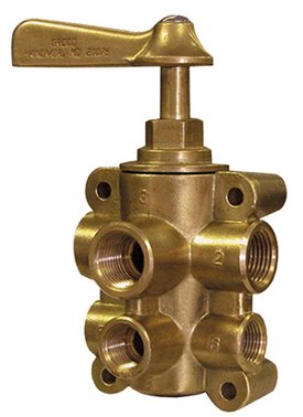
How about a Perko 6-way fuel selector valve for the primary supply and return selection. That way, you couldn't inadvertently have the supply and return crossed. It also provides an 'off' position that could be useful.
 

Attachments

  • fv-65038-400-wv.jpg
    fv-65038-400-wv.jpg
    87.4 KB · Views: 614
Dimer2

I have not seen a fuel pump setup in push mode either unless there is a priming [only] pump setup to aid with air purging which is then taken off line once the engine is running. Often, and my setup is this way, The priming pump is BETWEEN the main mud/water filter and the final filter on a bypass which is then shut off. Yes, a couple more ftgs but it sure helps at filter change time.

However, I noticed the pump positioning in the first series of schematics was in push mode and it is continued in push mode in the polishing circuit in the update.

It was intended simply as a caution to Skinny.


:thumb:
 
Engine and gen should not share a fuel supply. When running gen with main off, it can pull air backward through main injection pump, air loading it and then air loading gen. Since gen burns little fuel, it can be supplied from a dedicated tank.

Not clear which way the elec pump pumps: Torward the return fittings?? If so useless for repriming.

No return from gennie? If that is return going back to filter, should not do that, if air gets in system it will recycle. Should go to tank.

No valves to isolate primary filters from tanks.

Gen fuel filter redundant.
 
Tee off your genset before the filters. Ball valves from Home Depot. Make sure they have the correct thread, do not mix tapered and straight threads. Keep your dedicated filter.

You only need two filters for your single engine, put them after your manifold or however you choose to select your tank.

A small pump is better than a rubber bulb for filling your filters as they hold lots of diesel and you will be pumping until your arm aches to fill two. Unless, of course, you have gravity feed, then all you need is a shutoff. I like a little pump inline to bleed the injectors, or just manually pump your on-engine pump.

In order to "polish" fuel you need a strong enough flow to stir up whatever lies on the bottom and keep it in suspension. Big, expensive fuel pump. Don't bother. As others have said here, get it polished by professionals and wait another 40 years to get it done again.

Return fuel should be selectable for adjusting trim, BUT if you have a closeable balance line, not needed.

If you don't want to spring for a manifold, use ball valves attached with adel (sp) clamps to a nice painted piece of plywood with some nice labels (see Dymo 5200 thread). You can use fuel hose with good quality clamps. Many have. Replace the drain plugs in your filters with taps to prevent the mess of spilling and handling fuel - if you choose the filters without a clear bowl you can use the taps for "sampling."

You should not run your filters sequentially, that is a waste of a filter. You need to use one at a time so if one plugs you can isolate it and select the other and keep running. Your on-engine filter is the secondary. If a filter plugs, with the ability to isolate it you can switch out the filter element while enroute, while someone else drives. This part is fun and requires practice, it only ever happens when it's really rough and you are on a lee shore.

The vacuum gauges are good, they provide advance warning of plugging. "Water in the fuel" warning fittings are also good and provide advance warning of a failure.
 
The genset already has a tiny Racor which I could just leave as is. You are right, completely redundant. So I will leave that as optional. The big thing is that the Genset return goes to it which I'm not sure is correct or not.


As far as the Genset pulling fuel from the Perkins system, I'm sure the CAV on engine filter along with the Injection Pump have check valves to minimize this. Would putting a check valve in the T that feeds both of those eliminate those problems?


The fuel pump in this diagram would be pulling from the bleed valves and pushing into the tank returns. It is correctly installed this time as a puller through the filters :)
 
""""""As far as the Genset pulling fuel from the Perkins system, I'm sure the CAV on engine filter along with the Injection Pump have check valves to minimize this. Would putting a check valve in the T that feeds both of those eliminate those problems?"""""

Don't count on it.
I would still get that gen out of there and on its own circuit. If for some reason there is a problem in the gen. side, ie: air leak, you will not have any warning of impending trouble, main engine shutdown, and you will not know what has happened without a lot of flapping around when the main dies.

Trouble usually comes in adverse conditions and you want to be able to change filters with a couple valves, not also have to trouble shoot a problem with the gen. circuit backfeeding air.

Plumb that gen separately.

And run that gen. return back to the tank on its own line. It may be that way now but doesn't mean it's correct. I don't know about your gen. but some fuel systems move a lot of fuel compared to what they burn and the return fuel is very warm or hot. Feed that warm/hot fuel back into the filter immediately and there could be a serious power loss. The return to tank allows the excess fuel to be cooled long before it can go back to the engine.

Ski is dead on that a dedicated return is better. His point is something that I had not considered but he has a huge amount of experience. You may not know but he is a top notch mechanic who spends a lot of time helping on Boatdiesel also and one of his specialties is generators.

When you get a vacuum guage get one with a telltale needle. That way you do not have to be in the engine compartment to read it while the engine is running. The telltale will stay at the highest reading untill you reset it.

SMX Multi-Stage Fuel Fueltration™ Available Options

Home
 

Latest posts

Back
Top Bottom