Winter Project I: Charging System Upgrade

The friendliest place on the web for anyone who enjoys boating.
If you have answers, please help by responding to the unanswered posts.
GonzoF1 wrote:What do you make of this. Manual states:
Max. current starter 1150 Amps (!!!)
Sounds like "locked rotor current" and that does not represent typical starting loads.

In any event, that is not a long term load which is more likely around 500A or less and decreases very quickly as the engine turns over.

*

And by the way, solder does not get brittle. A poor soldering technique can produce a "cold solder joint" that looks granular and is mechanically and electrically defective but a solder itself does not get brittle.


-- Edited by RickB on Monday 27th of February 2012 02:57:20 PM
 
RickB wrote:GonzoF1 wrote:What do you make of this. Manual states:
Max. current starter 1150 Amps (!!!)
Sounds like "locked rotor current" and that does not represent typical starting loads.

In any event, that is not a long term load which is more likely around 500A or less and decreases very quickly as the engine turns over.

*

And by the way, solder does not get brittle. A poor soldering technique can produce a "cold solder joint" that looks granular and is mechanically and electrically defective but a solder itself does not get brittle.


-- Edited by RickB on Monday 27th of February 2012 02:57:20 PM

*Thanks for the correction, RIck. Hey, where have you been? Got a few email from me in you Inbox that I would love your expertise on. :-D
 
Just got back from a 5 week visit to Tahiti following up on the New Year's trip.
 
Just a quick update:

It looks like time is now my big enemy. What started as a electrical and charging system upgrade morphed into three other semi-major projects that required more time (due to back-and-forth trips, test fits, and other challenges) than anticipated. Not to mention the cost have gotten a little high and I need to recover from them.

That said, Now that I have a new raw water system and battery tray that will hold up to seven batteries (once I fix a minor screw-up), I plan to sort of prop up my old charging system for the early part of this season. I dread spending all this time on projects that are supposed to enhance the boating season, then feel the pressure and some guilt if it causes the loss of any possible boating enjoyment.

My plan is to clean up all the connections with new high quality lug connectors and the addition of HD Blue Seas battery switches in the lower step for on/off and battery combine. I think that I can take small steps toward the goal over the summer by adding more buss bars, the new Iota charger and heavier wire runs. Besides that, I tested the batteries with a 130A load tester and they came up "Weak", so I will need to gather the cash to replace them too.

In the meantime, I have some wire samples on the way from Harbor Specialists so I can see the quality and decide what connectors I need to order from Grainger. I also really need to crack open the fuel tank access plate and try and clean the sludge out sooner rather than later. So for the time being, the big wonderful project upgrades will have to wait. I just didn't expect the raw water rig to take so long AND that I would need to build a new battery tray. Oh well... trying to learn patience these days and this is my first test of what I have learned.

For now, here is the new battery tray all epoxied and painted and ready to go. :-D (measure 50 times... cut once... and STILL make it 1/2" too short! Dammit!)


tray by GonzoF1, on Flickr
 
Sounds like "locked rotor current" and that does not represent typical starting loads.

Typical or not , the wiring must be able to take this load for an instant on every start .

IF crappy terminals or loose connections are in the circuit they will be heated , causing the resistance of the wire to be higher during the rest of the start sequence.
 
Right... I think.

Anyway, that reminds me that one of the other upgrades this season is to replace the power hungry direct-drive AC Delco starter with a much more miserly gear reduction starter I bought new last year as a backup. Move the Delco to backup duty to try and reduce the overall DC load.

Tom-
 
FF wrote:Typical or not , the wiring must be able to take this load for an instant on every start .
That is more than a bit misleading. If the wiring were sized to carry the locked rotor current it would require 4 or 5 4/0 cables in parallel.

Adding the words "for an instant" means that wiring sized for a typical starting current with a rapidly diminishing inrush of 500A or so is adequate and normal accepted practice. The temperature rise in a normal start is negligible.

What size conductors do you think are inside the starter motor itself?
 
Here are some pics of what I am up against and why this whole thing started.

These are bits I cut off last week to bring home and size. The smaller it the cable going to the DC panel and the larger gauge is the starter positive wire.


a by GonzoF1, on Flickr
A closer inspection of the CURRENT state of my starter lug! YIKES!


b by GonzoF1, on Flickr

Removal of the tape is even more scary. How anyone thinks this is ok is beyond me.


c by GonzoF1, on Flickr

The cables are coming from one vendor and the lugs are coming from another. The cable vendor's lugs are open-end and I would rater use the MUCH higher quality Quik-Cable lugs. So I got samples of all of them to test the fit. It all came today :)


d by GonzoF1, on Flickr

Finally, I made my first crimp. It looks like the 1/0 lug fits best, but I may try the 2/0 on it too and see how it goes.


e by GonzoF1, on Flickr
 
Use the proper lug barrel size for the wire or you will again have a poor crimp. If the barrel is too big it will not compress properly. Even though you can't pull it off you will have a poor crimp with gaps that will later cause hard to find trouble.


Part of the trouble with the old ones is the installer should have put the crimper anvil on the other side. Instead he split the brazed joint and of course the strands should have come all the way through to be a bit proud of the barrel.

Anyways you will have fun and know it will be better for the future.
 
Thanks Clark...

I have a question for the expert though. Can the lug be too small? For instance, the 3/0 wire can be massaged into a 2/0 lug. 4/0 wire can get into a 3/0 lug. Etc. That makes me wonder if my test wire should have a 2/0 lug on it. It was a bit of a tight fit to get into the 1/0 lug shown above.

Tom-
 
Proper crimpers are great , but few own them.

Set the crimp tight with a ground dull chisel and simply dunk the end in a ladle full of solder.

A propane torch will melt a coil into a cast iron ladle .

The requirement is the terminal end must be mechanically secured AND electrically secured.

The above works , and proper color shrink tape makes it look professional.
 
Keep in mind the lugs are engineered to work as part of a system. So is your crimper. Use the proper parts correctly and you will have a good job, otherwise maybe not.

Yes it is possible to massage a wire into the next size lug barrel down, SOMETIMES.

However, these lugs , assuming you have good quality lugs, should be bought for the wire size to work properly.

There is more to it than just getting the wire in.

You will actually thin the copper barrel in the crimp area, not noticeable to you maybe, but the result could be a less than satisfactory grip on the conductor and the barrel subject to later cracking.
 
Another quick update:

I came down a day early this weekend and spent all day yesterday "updating" the wiring as described above. I made new jumper wires between the four house batteries, new lugs on all the welding wires and at both the starer's lug and the primary ground lug.

One thing I didn't anticipate was that the new lugs are FAR thicker than the old. Seeing that the new plan is just to (and I hate to use this term) prop it up for the Spring boating season, I didn't think that more than one lug on the battery terminal would be all that will fit. (yes, I know you shouldn't do that)

Sooooooo... The workaround is to use a couple of 600A Blue Sea buss bars and divide the starter battery all up (main starter, genset starter, and windlass).

The upside to all of this is this... In the past, it seemed like the starter struggled (albeit only a little) to spin-up the Perkins 6.354. When I tested it yesterday, it has NEVER started stronger. I mean, I was surprised at how strong she rotated and started!

Today I change coolant and oil for the season and we should be set. I'll get some pics taken today of the new wiring setup.
 
I was surprised at how strong she rotated and started!

You might have had the same results by just cleaning everything.

One tip is to only use COPPER to join terminal ends .

Copper not SS or brass or bronze , sold on line for high voltage use tho ideal for most boat stuff.

If you have a friend that works for a power company , Creative Begging , should garner a bucket full of the real thing.

FF
 
I tried to install the battery monitor last weekend. apparently, the house panel has it's own ground (that STILL makes it to the block thru a yet-to-be-determined route and I want to think it's thru the bonding system). So the ground I planned on using doesn't show what the house load is (or any load for that matter, except when I try to start the main). Sooooooo, I need to move the panel ground to the main ground buss bar and bring a ground wire over from the house batteries. Problem is, I am all out of lugs the correct size. *heavy sigh* There sure are more wires, even for my summer temp job, than I thought there would be. Dang.

I will try to get those pics this weekend of the progress. Bess keeps forgetting the camera.
 
I will try to get those pics this weekend of the progress. Bess keeps forgetting the camera.

Yea blame it on her. I think it was Jello's fault myself.
 
One thing I didn't anticipate was that the new lugs are FAR thicker than the old.

NAPA and other sources have terminals that change the common battery barrel terminal
to a style of flag terminal.

NAPA catalog calls them "military" style terminals , cheap by the box . They fit well so a box of P and N are required to do a good job.Perhaps $5.00 each.

FF
 
UPDATE - As I said above, I have had to "shortcut" the project a little to get Skinny Dippin' up and going for the season and control the overall costs. I plan on taking on the few remaining pieces of this project a little at a time over the course of the summer.

I still need to mount all this to a breadboard of some kind, add the new Iota charger, move the alternator wiring to the house bank, add the echo charger, and generally clean up the install. Although, I am surprised at how many wires I have ended up with. It's looking like it's not going to be NEARLY as neat of an install as I had envisioned it being. Pity.

I just wanted to add a few more pictures to the archive.

1) The switch bank in the stairs
2) New battery cables (new batteries since pic was taken)
3, 4, 5) A few shots of the layout
6) The pass-thru up to the switches and wires over the batteries
 

Attachments

  • switchstep.jpg
    switchstep.jpg
    64.6 KB · Views: 75
  • proj1.jpg
    proj1.jpg
    86.7 KB · Views: 73
  • proj2.jpg
    proj2.jpg
    94.1 KB · Views: 73
  • proj3.jpg
    proj3.jpg
    102.2 KB · Views: 66
  • proj4.jpg
    proj4.jpg
    104.2 KB · Views: 84
  • proj5.jpg
    proj5.jpg
    83.5 KB · Views: 78
Others contemplating a project like this might be interested to know that hi-quality manufacturer BEP produces a range of Battery Management Panels that greatly simplify battery switch mounting and cabling, incorporate buss bars and provide for circuit breakers for always-on/24 hour services: take a look here: 800-MS1 - Battery Management Panel

Where did you get to in deciding whether to power your davit from House or Start bank? I'd recommend from Start, as the short-burst/high current draw is more like a Start load than a deep-cycle load. If you haven't already, in the future you can use a battery type well suited to Start/Davit/Thruster loads such an Optima spiral-wound AGM. You already have the Balmar Duo-Charger (excellent choice) which can be programmed to suit the charge profile of this kind of battery. And yes, my own vessel is set up this way. Here's a pic of my charging system, which involves combining the output of two alternators with a Balmar CenterFielder and 2 x Balmar Regs; and charging Start & Genset batteries with Duo-chargers.
 

Attachments

  • Full Installation View.jpg
    Full Installation View.jpg
    124.4 KB · Views: 96
Sort of messy for my tastes:angel:
 
Sort of messy for my tastes:angel:

If you are referring to my wiring job... I agree. It's sort of messy for my taste too (actually WAY messier that I had hoped). But, with cost spiraling out of control, time running out to get back to this season's boating, the current long-run wires installed when the boat was built which made them impossible to swap out, and a few other unanticipated complications, I really needed to get the system to a point where it was working. Moreover, is IS a VAST improvement over the previous setup. More complex, but I am now more comfortable that we can stay out on the hook for longer periods. I also have a must greater knowledge of the entire system from one end to the other.

Would I like it to be all laid out proper? You betcha. However, as with everything in boating, a compromise needed to be made. Perhaps someday in the future we can live closer to the boat so I can spends all the days of the week (after work) working, test fitting, adjusting, refitting, and getting projects perfect. Now, however, we are only able to get down on weekends (usually every other) and it REALLY slows the process down.

Tom-
 
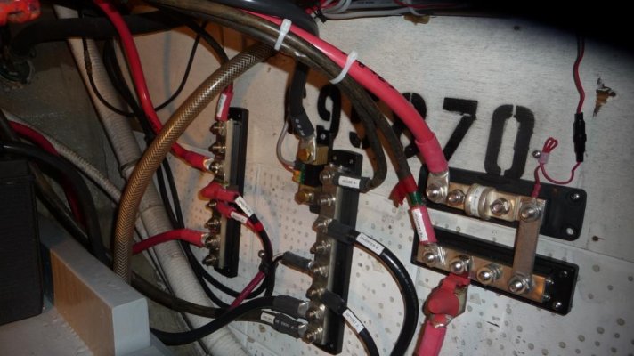
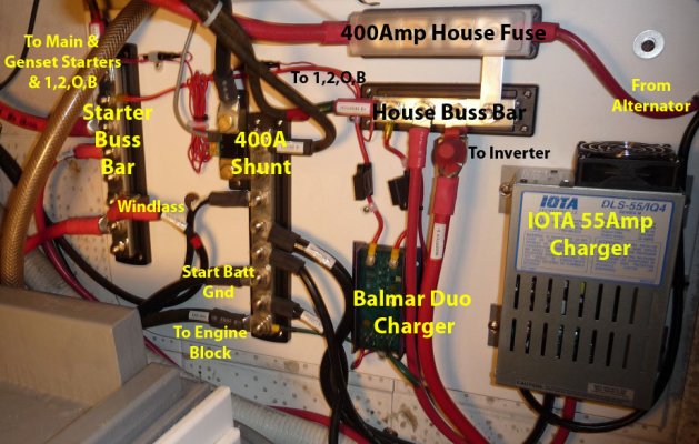
Here is the final-ish layout mounted to starboard. It will stay like this for the season. I'm calling it done... yes, it's messy.
 

Attachments

  • wiringfinal.jpg
    wiringfinal.jpg
    73.8 KB · Views: 141
Tom, your wiring looks fine! Wish mine were anything near that. Actually I was poking fun at Aquabelle!!
 
Not sure if this will help or how well it will look posted, but here is the same pic as yesterday, but I added a few labels to it. At some point, I may put together a final schematic for it. I guess it would be nice for a future buyer to know WTF I have done. :socool:

Tom-
 

Attachments

  • wiringfinallabels.jpg
    wiringfinallabels.jpg
    184.2 KB · Views: 173
Just wanted to make a posting to this subject thread so I would remember to come back and review it. I may have such a battery project coming up soon.
 
Wow! Phoenix has risen from the ashes!

FWIW--- the system has been flawless in the two years since completion.
 
How has the Iota charger held up? This winter it's my turn to tackle electrons.
 

Latest posts

Back
Top Bottom