Fuse sizing for inverter

The friendliest place on the web for anyone who enjoys boating.
If you have answers, please help by responding to the unanswered posts.

timjet

Guru
Joined
Apr 9, 2009
Messages
1,920
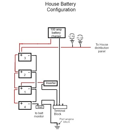
I installed a cheap 1200 watt continuous/ 2000 watt surge Chinese inverter primarily to watch TV on the hook. Paid 90 bucks for it, so yea it's cheap. Bought at harbor freight.

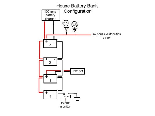
The battery cables are #2 AWG 15 feet long. If my calculations are correct, for the 2000 watt surge I would need a 166 amp fuse installed as close to the battery as possible.

If amps = watts/volts then amps = 2000 watts/ 12 volts which yields 166 amps. Correct? :dance: or :nonono:
 
Using NFPA 302 Table 9.12.5(b) Allowable Amperage of Conductors for Under 50 volts You are about right. The table of amperage's is based on temperature rating of conductor Insulation and inside or outside engine spaces.:D
 
As obthomas said, you are about right, probably a bit more current due to the battery voltage dropping below 12V and 5% inverter losses, but close enough.

But just running a TV and assuming it is a medium size LCD, not a CRT or a plasma, you will see less than 100 watts from the inverter, maybe 10 amps DC max. With the proper size fuse to protect it, 18 gauge wire will work.

David
 
I'm really surprised that the installation instructions didn't mention the fuse size and cable size for installation. The instructions for my Xantrex are very specific.

15 feet is a very long run for that much current and it's really 30 feet if you didn't include the negative return. You may have enough voltage drop in the cables to shut down the inverter if you put a serious load on the inverter.

It's best practice to make the DC cables as short as possible to minimize voltage drop. There is very little voltage drop in the 120 volt AC wiring. It's just like in your home.
 
Guys, like David said, based on what the load is here we're building a mountain. It's a TV . fuse it as you are and let's move on.

Sent from my Nexus 7 using Trawler
 
Guys, like David said, based on what the load is here we're building a mountain. It's a TV . fuse it as you are and let's move on.

Sent from my Nexus 7 using Trawler

It's not a TV, it's a 2,000 watt peak inverter. Who knows what might be plugged into it.

If you're going to do something you might as well do it correctly. That means follow the instructions and ABYC standards. Use the correct sized cable and correct circuit protection.
 
My point is the op asked a simple question and we're turning this into a !another long drawn out issue. Just for the record I also agree that all projects should be done correctly.

Sent from my Nexus 7 using Trawler
 
I ordered a fuse block that attaches directly to the battery with a 125 amp fuse. Like this: Blue Sea Systems Terminal Fuse Block

Sounds like you're well protected, Tim. The 125A fuse will blow before causing wiring damage...that's the key. Your 1200W continuous power is 100A at 12V. If you hit the peak of 2000W for a sustained period, you will blow the fuse. No problem...that's the intent, right?

If you add additional loads to the circuit besides the TV and notice the inverter humming from low voltage, consider upgrading your cable size. Until then, sounds like you're good.
 
To interrupt BIG juice the class T fuse and fuse holder has the best chance.
 
If a #2 wire is rated at lets say 115 amps over 30', size the fuse as to not allow the wire to become the fuse, so possibly 100 amp fuse.

Conall
 
I have a generator and don't need no stinking inverter.
I have Chinese LEDs and love them.
I have guns onboard.
Diesel rules.
I despise gel cell batteries
Teak decks suck
 
I'm with Ron size the fuse for the inverter not the TV. You might as well run the TV directly off the DC buss and have -0- inverter losses or have a chance of the inverter bypassing the correct source ABYC standards for a marine inverter.
Most TV LED TFT units smaller than 26" use a wall transformer power supply that feeds the TV 12-14VDC. The TV has built in voltage regulation and most have a Zener diode which protects from over-voltage, spikes or transients from the DC buss in the vessel. Properly size the DC fuse to the TV and it's internal protection will at worst cause the DC fuse to blow feeding the TV power.
Bill
 
Last edited:
Motors starting are usually the cause of a high current requirement.

Check the fuse size with the batt partially discharged and run your blender or vacuum.

.
 
Please speak plainly I (don't know about others) am not a mind reader:D

I have a generator and don't need no stinking inverter.
I have Chinese LEDs and love them.
I have guns onboard.
Diesel rules.
I despise gel cell batteries
Teak decks suck
 
Will the battery monitor register the inverter DC use.

Thanks guys for all your input. I got a 125 amp fuse and will finish the install early next week. I don't think we will use the inverter for anything else but the TV. I did try our 1200 watt pop corn popper and it worked. That maxed out the inverter, but again it worked. The TV probably pulls max 300 watts.

I do have a question concerning the battery monitor and the inverter. I haven't had a chance to check it out yet, but will the battery monitor register the inverter use (DC side) with the hook up I've got. The inverter is connected to the positive terminal of one of the house batteries and the negative is connected to the negative side of the same battery. My house bank consists of 4 AGM batteries connected in parallel. The shunt of the battery monitor is connected to the negative side of one of the house bank batteries but not the same one as the inverter.

Below is a schematic.
 

Attachments

  • House battery configuration.jpg
    House battery configuration.jpg
    44.3 KB · Views: 112
Last edited:
Motors starting are usually the cause of a high current requirement.

Check the fuse size with the batt partially discharged and run your blender or vacuum.

.

That makes no sense. The fuse should be sized for the capacity of the DC cables unless the inverter manufacturer specifies something less.

It doesn't matter if the battery is partially discharged or the blender or vacuum is running. There is no need to do anything other than reading the instructions or looking up the capacity of the cables.
 
I have a generator and don't need no stinking inverter.
I have Chinese LEDs and love them.
I have guns onboard.
Diesel rules.
I despise gel cell batteries
Teak decks suck

Dang. . . A man after my own heart :iagree:.. .. .. .. obthomas for president !! :eek: LOL
 
Last edited:
I do have a question concerning the battery monitor and the inverter. I haven't had a chance to check it out yet, but will the battery monitor register the inverter use (DC side) with the hook up I've got. The inverter is connected to the positive terminal of one of the house batteries and the negative is connected to the negative side of the same battery. My house bank consists of 4 AGM batteries connected in parallel. The shunt of the battery monitor is connected to the negative side of one of the house bank batteries but not the same one as the inverter.

Below is a schematic.

Tim, you need all your grounds connected downstream from the shunt. Can you move the inverter ground to a point past the shunt? I added a terminal block after the shunt to accommodate all the grounds cleanly.

131690817.FfaFer0o.jpg


Also take a look at your charger neg lead. It needs to be downstream from the shunt so that all loads and charges pass through the shunt when passing to ground.

131692384.U2NRsNEI.jpg


Here's a great tutorial with good illustrations.

Installing A Battery Monitor Photo Gallery by Compass Marine How To at pbase.com
 
Last edited:
Thanks Al for catching that.

Below is the revised schematic.

Do you know what size negative terminal block I would need for the 100 amp charger and 2000 watt inverter. Under the below schematic I don't think the alternators will register on the battery monitor, I have no idea where the negative leads go to on the alternators probably the the engine blocks.
 

Attachments

  • House battery configuration.jpg
    House battery configuration.jpg
    53.9 KB · Views: 78
Last edited:
OK, well now that I've had time to look at my other electrical schematics, I'm not sure my battery monitor is going to be much help.

There are several negative common bus bars through out the boat maybe 15 or so. I don't know where these negative bus bars connect but I know they can't connect after the shunt.
 
Last edited:
Negative shunts and with bypass leads create a challenging problem. That's one of the reasons the BalMar SOC battery gauge is being debated in this forum and many others. I used a 600-800 amp rated negative buss bar(s) made by BlueSea to tie my negatives together before the shunt.
Bill
 
Last edited:
Do you know what size negative terminal block I would need for the 100 amp charger and 2000 watt inverter. Under the below schematic I don't think the alternators will register on the battery monitor, I have no idea where the negative leads go to on the alternators probably the the engine blocks.

1. Blue Seas 2303 terminal block is rated for 150A. I used a 2104 that is oversized at 600A. This is what I have.

2. There's no neg lead from the alternator. Its positive lead goes to the battery, and the ground is the engine itself.

OK, well now that I've had time to look at my other electrical schematics, I'm not sure my battery monitor is going to be much help.

There are several negative common bus bars through out the boat maybe 15 or so. I don't know where these negative bus bars connect but I know they can't connect after the shunt.

All your negative blocks should be connected to the ground through the battery ground leads. If you disconnect the house bank ground cable, all these systems should be dead. If so, you're set up properly. If some systems are still powered, disconnect the house pos cable to see if they're still powered. If they're now dead, you have a secondary ground set up somewhere and the battery monitor won't read those loads. If they are still powered, then they're being powered through the start or another battery and the battery monitor won't read those loads.

PM me if you'd like to talk it through on the phone.
 
Last edited:
Negative shunts and with bypass leads create a challenging problem. That's one of the reasons the BalMar SOC battery gauge is being debated in this forum and many others. I used a 600-800 amp rated negative buss bar(s) made by BlueSea to tie my negatives together before the shunt.
Bill

By "before the shunt", do you mean between the engine ground and the shunt itself?

Yes, the Balmar SmartGauge had no shunt and learns your battery bank's condition through voltage sensing alone. It like having a more accurate fuel tank guage, but not having the fuel flow meters. You can see how low your battery is, but you can't monitor the rate of consumption without a shunt system like the Victron or LinkPro.
Yes between the engine ground and shunt.
I haven't installed the BalMar SOC meter yet it will be interesting to watch how it behaves.
I also use the 2104 buss bars.
Bill
 
Last edited:
The main thing to remember with a battery monitor shunt is this. NOTHING is connected directly to the battery negative but the shunt on the battery bank you are trying to monitor, usually the house bank. EVERYTHING is connected to the load side of the shunt, usually on a negative buss bar. If this is done, the monitor will see everything going into and out of the battery bank no matter where it comes from. (inverters, alternators, battery chargers, etc.)
 
The main thing to remember with a battery monitor shunt is this. NOTHING is connected directly to the battery negative but the shunt on the battery bank you are trying to monitor, usually the house bank. EVERYTHING is connected to the load side of the shunt, usually on a negative buss bar. If this is done, the monitor will see everything going into and out of the battery bank no matter where it comes from. (inverters, alternators, battery chargers, etc.)

YES!

The diagram shown does not monitor the batt charger or inverter , rather important items.
 
Yes both Brentt and FF are correct. All negative leads must connect to the Load side of the shunt.

Below is my revised schematic.

Notice I connected the Engine ground wire directly to the Load side of the shunt. I also connected a negative bus bar to the Load side.
Reason; the bus bar is rated for 150 amps. The shunt is rated at 500 amps. I thought is would be better to put the starting loads at the higher rated shunt instead of the lower rated bus bar.
 

Attachments

  • House battery configuration.jpg
    House battery configuration.jpg
    54.8 KB · Views: 86

Latest posts

Back
Top Bottom