2 many electric questions

The friendliest place on the web for anyone who enjoys boating.
If you have answers, please help by responding to the unanswered posts.

Sunset

Senior Member
Joined
May 12, 2013
Messages
278
Location
Canada
Vessel Name
Manatee
Vessel Make
1976 Albin 25 DeLuxe
OK, I'm going to post a few pics - the first one is the 1971 A25 wiring diagram, followed by my alternator, starter, then the existing wiring (front), then the back of the panel. I am going to have to upgrade things: (a) install my ACR and on-off switch; (b) install my Promarine 12A charger; (c) rewire battery wires and install proper circuit protection; (d) rewire the circuits.

I'll ask a few questions in the next post.
 

Attachments

  • Albin 25 elec diag-page1.jpg
    Albin 25 elec diag-page1.jpg
    154 KB · Views: 1,491
  • AltWiring.jpg
    AltWiring.jpg
    102.5 KB · Views: 233
  • StrterWiring.jpg
    StrterWiring.jpg
    110.4 KB · Views: 167
  • WiringFront.jpg
    WiringFront.jpg
    104.3 KB · Views: 194
  • PanelBack.jpg
    PanelBack.jpg
    148.8 KB · Views: 184
Although everything (except the anchor light) seems to function, I think it's clear why the system cries out for improvement. I've been reading the books and the interwebs on the subject and deficiencies include a lack of circuit protection in the battery room, unidentifiable circuits, electric and electronic add-ons that are not integrated into the system, and so on. Both batteries are relatively new.

Some questions I have:
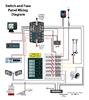
Diagram:
- what is the unit inserted between the Pos battery terminals? - not evident in the actual pic of the batteries.
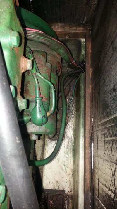
- I want to increase the size of the alt-starter cabling, but which wire (looking at the starter pic) is the right one?
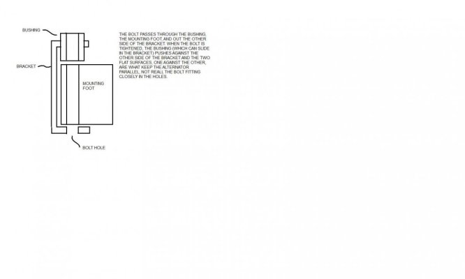
- I suspect the alt pulley is out of alignment
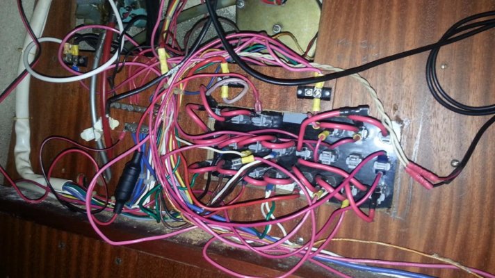
Front wiring pic:
- Cannot figure out what all those small wires to the left and right of the Pos bus are. The Pos bus is the black disc and the black wire attached to it comes from the switch to feed the panel above.

Panel back:
- Best way to identify what is what? Or just take it all out ans start over, incorporating the VHF and depth into a new breaker/switch panel?
- The horn, fuel pump and bilge pump have toggle switches on the console already.

Basically, any input to give me hints, shortcuts etc. greatly appreciated! :)
 
Your very first question, the item between the pos. battery terminals in the diagram. I don't know what the symbol means (maybe Swedish) but that is basicly where your new ACR goes.

The red wire on the battery (in the picture) is something that wants to stay on when the switch is off. Might be bilge pump, anchor light, or alarm. That wire should be fused within 7" of the battery. Only leads that are part of the starting circut need not be fused.

Usually, but not always, there are two smaller terminals behind the battery switch. These control the field wire to the alternator so that if the switch is turned to off while the engine is running, you won't burn out your alternator. Does your swicth have these?
 
Last edited:
The alternator is definitely out of alignment. You are going to have a problem with the belt wearing out in short order. If you can't move it back you may need to get another.
Bummer it looks brand new.

I would get rid of that battery switch and go with 3 simple on off switches.
One for the house.
One for the starter.
One to combine all banks.

With the 3 switch system all you will need is a combiner for the charger.
No need to worry about where the switch is set. It is either on or off.

If you do start over label each wire use a sharpie marker label both ends.
it sure makes it easier to identify what you have at a glance.

As to the cable for the alt & starter I would replace them both. With them both painted green it is hard to tell what you have.

You could take them off and have them made up or (I would suggest rent a crimper I don't know about you but I have enough one time tools)

One last thing spend the money on quality splices. A butt splice or end crimp is usually the weakest link.

SD
 
With regards your crooked alternator:
I have seen this many times on retrofitted Delco, single foot, alternators. The alternator is not held in alignment by the bolt even if there are two bosses on the engine for the bolt to go through. In most cases the foot is pushed up against one boss by an ingenious system of bushings where the bushing passes through one boss and pushes against the foot, forcing the other side of the foot against a flat surface as it is tightened. Therefor it is the two flat surfaces that hold the alternator parallel with the engine block. Look for this and if there is not too much wear on the surfaces from running cocked you may be able to set it straight with no more than the proper bushing. The holes may be elongated from running this way but it is the flat surfaces that count.
 
the item between the pos. battery terminals in the diagram . . . where your new ACR goes.

Makes sense.:thumb:

The red wire on the battery (in the picture) is something that wants to stay on when the switch is off. Might be bilge pump

Good bet. I will follow it when the temps rise above absolute zero.

there are two smaller terminals behind the battery switch. These control the field wire to the alternator Does your switch have these?

Not at this time. Perhaps I could install such a wire with my new on/off switch.
 

Attachments

  • AddBatt.jpg
    AddBatt.jpg
    11.6 KB · Views: 629
I would get rid of that battery switch and go with 3 simple on off switches.
I see the benefit of having that flexibility but my system is pretty basic so for now I going to go with the single on/off as above pictured.

If you do start over label each wire use a sharpie marker label both ends.

Definitely. Just have to choose the system among the various options of labelling.

As to the cable for the alt & starter I would replace them both. With them both painted green it is hard to tell what you have.

Agreed. There is a cable from batt neg to grnd and a cable from batt switch to starter. and the small green wires at the top of the starter go from and/or to the alt. But they are sheathed together and I don't know which is the one that carries the charge back to the battery via the charger.

You could take them off and have them made up or (I would suggest rent a crimper I don't know about you but I have enough one time tools)
Yes I have enough one-time tools. I made a cable at West Marine last month, 18 inches, AWG #2, and the bits cost me more than if I had ordered it premade from Genuinedealz, who I believe do a very good job of it. I think I'll go that way. I have bought a decent crimper for the wires that don't require a mega crimper.
 
With regards your crooked alternator:

I am the kind of guy who is willing but not so able when it comes to mechanical. I did a lot of work (well, for me) on my bikes before switching to boating, but for the alt I think I should have it looked at by someone who does this for a living. I also need to have my mechanical fuel pump disabled and bypassed as it is leaking fuel. The electric pump will be fine on its own.
 
I would hate to make specific recos base on a couple of blurry pics on the interweb, but the big picture, to me anyway, is that it looks like you could REALLY do yourself a favor and do a complete tear-out and rebuild. I see a lot of sloppy unlabeled wires, corroded connections, and non-waterproof connectors. The other HUGE plus about a complete refit is that when you are done, you will have a 100% working knowledge of your boat's electrical system.

A couple of BlueSeas terminal blocks, a buss bar or two (+.-), a box of heat-shrink spade connectors, a few spools of wire (BTW- the new "standard" for DC positive is yellow... even though I didn't follow it when I did mine), and a few weekends on your back/belly/knees and you should be golden. Figure about a few hundred bucks in parts should do it. Your system doesn't look very complex, but don't let that fool you. Be careful. A fire from a simple mistake would suck like nobody's business.
 
Greetings,
Mr. Tom. "the new "standard" for DC positive is yellow" I think that should be negative should it not? If, in fact you are correct, what rocket scientist suggested THAT one? Red is HOT and unless you're talking banana peppers, yellow is not.
Mr. S. I fully agree with Mr. Tom. Replace everything.
If I ever get around to it I'm going to make use of this stuff.
http://www.cabletiesandmore.com/wireloom.php
 
Last edited:
Greetings,
Mr. Tom. "the new "standard" for DC positive is yellow" I think that should be negative should it not? If, in fact you are correct, what rocket scientist suggested THAT one? Red is HOT and unless you're talking banana peppers, yellow is not.

Ooops... Right. SORRY!
 
Greetings,
No problem Mr. Tom. I know how you like your artisan brewski's AND you aren't getting any younger....
tumblr_lwg6nhGmaF1qzjix8.gif
 
you could REALLY do yourself a favor and do a complete tear-out and rebuild.

I absolutely agree and I am eager to roll up my sleeves and get to it. If only it were a little bit freakin warmer out there . . . :rolleyes:

I have to decide, as a rookie, whether I can put it back together without missing a crucial link. So before I start ripping I am trying to understand what is there right now. Hence my questions about all those pesky little red and blue wires that don't conform to all the beautiful and logical diagrams that I am finding. Like this: (can't find the proper sized one)
 

Attachments

  • Typical Wiring.jpg
    Typical Wiring.jpg
    2.9 KB · Views: 528
Last edited:
Does this make sense - in relation to the installation of the ACR and switch?:

A boat's wiring diagram can aid in the specific location of the alternator charge wire and the accessories/ignition wire (wire that feeds the boat's fuse panel and accessories). Typically, these are located at the positive lug on the starter solenoid. After identifying the accessory/ignition feed wire, it should be disconnected and wired to the the #1 (main battery) terminal with at least the same size gauge electrical wire. Then from the #1 isolator lig run another wire to the #1 positive battery terminal.

Getting Your Boats Battery System Ship Shape

If so, how would I identify the correct wires from the diagram based on the pic of the starter below:
 

Attachments

  • Albin 25 elec diag-page1.jpg
    Albin 25 elec diag-page1.jpg
    154 KB · Views: 140
  • StrterWiring.jpg
    StrterWiring.jpg
    110.4 KB · Views: 128
Last edited:
Greetings,
Mr. S. Forget the picture. Get yourself a VOM (Can be had for ~$20 or less), read the instructions or look up testing procedures on the net, grab a roll of masking tape and some Sharpie markers and label all the old wires as you identify where they go and what they do. THEN you can start on a rewire.
 
Good advice from RTF, take it to heart with one minor addition... the type of meter.

Make up a loooonnnng lead with an alligator clip on one end and a meter plug at the other so you can trace each wire.

Disconnect the batteries, disconnect the single wire you are trying to identify at some point and connect the long wire to the clip. Now look for a very low resistance at the place you think the other end is. Make sure the meter is set at a range that will not give you a false reading. Digital VOMs are nearly useless for some work like this because they are too "sensitive" and are easily misinterpreted by inexperienced users.

Get a $2 Radio Shack analog meter instead.
 
Thanks for pitching in RTF and Rick - OK, I think that is the direction I need to go since all wires around the engine disappear into sheaths, making them impossible to trace physically. I do have a digital VOM meter and a circuit tester. I never thought of the disconnect-check resistance method. That should help me identify all those other circuits as well.
 
Disconnect - check continuity - the resistance might tell other stories. If you know the ohms per foot of the wire you are checking you may be able to determine if there are other connections in between or a high resistance connection.

Practice will make you a good troubleshooter.

If you want to go a bit more high-tech, a "fox and hound tracer" can be a big help to localize the wire among a bundle that is otherwise difficult to follow. The scent can be tricky to follow though ... the hounds don't always catch the fox.
 
With regards your crooked alternator:

I took a closer look at the alternator today while trying to trace various wires. Am I correct in thinking that the belt is intended to run off the toothed section of the fly? Because the belt is certainly well-toothed itself. I direct the reader's attention to the lower right foreground where the mounting foot of the alt is attached to the green mounting arm of the engine. There is a great huge square shim there.

Seems like - remove the shim?? :confused:
 

Attachments

  • AltBelt.jpg
    AltBelt.jpg
    83 KB · Views: 113
Last edited:
Greetings,
Mr. S. The toothed belt is NOT meant to run on the gear (ring gear for starter I suspect) on the flywheel. The belt, in spite of the "teeth" is meant to run in the smooth pulley section of the flywheel where, in fact, it appears to be.
As far as the shim goes, tough call from pictures only.
 
Last edited:
Thanks RT - saved me from barking up the wrong tree. From that angle it doesn't look quite so out of whack.
 
Greetings,
Mr. S. The majority of us have previously enjoyed vessels (read used/abused or not so much). I would think it unheard of that any vessel has escaped the attentions of so-called experts/rocket scientists/I heard from someone's/this should work and good enough's. That being said, everyone wants to put things right without falling into the DPO (damn previous owner) category.
A certain amount of expertise can be acquired by self education and just doing with appropriate reference material at hand and tasks accomplished in a safe, economical and timely manner so keep those questions coming BUT keep VERY MUCH in mind free advice given to you on the internet is worth exactly what you pay for it.
 
Thanks RT - I have learned that lesson from years of internet motorcycle maintenance. One reason I did take a Power Squadron electrical course. The internet helps when it comes down to the short strokes of a particular situation - such as the belt question above, and other useful tips I have been getting. I do try to get multiple inputs so it becomes easier to separate wheat from chaff. Whatever chaff is.
 
I took a closer look at the alternator today while trying to trace various wires. Am I correct in thinking that the belt is intended to run off the toothed section of the fly? Because the belt is certainly well-toothed itself. I direct the reader's attention to the lower right foreground where the mounting foot of the alt is attached to the green mounting arm of the engine. There is a great huge square shim there.

Seems like - remove the shim?? :confused:

No, the belt does not run on the ring gear as has been said.
The mounting foot I was refering to is on the opposite side of the alternator (180 degrees) from where you are looking. What you are looking at is the belt tensioner bracket, and yes the huge "shim" is not necessary or good, but it is not the problem either. I need to find or draw you a sketch of what I am talking about with the mounting bushings on Delco holding the alternator parallel.
 
It's just not accessible under there; I can't even figure out the cable / wire routing as it/they wind their ways around the alternator in and out of sheaths.

However I was able to track 4 after-installed rogue circuits: bilge pump/switch/float; VHF; Depth sounder.
 
Last edited:
Greetings,
Mr. B. I agree with your comment re: "the huge "shim" is not necessary or good..." but we don't know what the mounting foot looks like nor even if the correct alternator is in fact being used. Could be a jerry rigged mount which necessitated that big shim. Looks like the bracket is at the end of the adjustment as well. Lots going on that has to be fixed. In an ideal install the bracket should look something like this.
th


Mr. S. You say you can't see anything but you're going to have to remove the alternator, adjusting bracket and mounting foot the whole works in any case and start afresh at which point you will be able to see what's going on. Don't forget to disconnect your battery and label all your wires. Fun eh?
 
It's just not accessible under there; I can't even figure out the cable / wire routing as it/they wind their ways around the alternator in and out of sheaths.

However I was able to track 4 after-installed rogue circuits: bilge pump/switch/float; VHF; Depth sounder.

Here is the sketch on what should be happening under your alternator. To get at it, you may have to remove the tensioner bracket (which needs to be delt with anyway) then remove the belt, then swing the alternator over/down to see the mounting foot.

Good picture Firefly
 

Attachments

  • ALT. MTG..jpg
    ALT. MTG..jpg
    33 KB · Views: 72
Last edited:
OK thanks guys. I guess I'll bite the bullet and dig in there. I removed the batteries today in the hope of tracking the blue wire that disappears beneath the batt box - no luck in that regard so far. But at least the batteries are out and all battery conductors labelled.

I'll have to wait for the temps to get above 5C again . . .
 
I see the benefit of having that flexibility but my system is pretty basic so for now I going to go with the single on/off as above pictured.

Keeping your house and start systems separate will give you greater reliability/piece of mind while your out on the water and can be easily accomplished. I rewired my 1982 28' Carver several years ago using this panel. Simple, takes very little space. House battery wired to the "House" breaker giving you needed protection. Start battery wired directly to the two position switch eliminating the unreliable off-1-2-both switch. You also get the emergency crossover combining both systems for emergency start. Great project, look forward to seeing your final product!

8080.jpg
 

Latest posts

Back
Top Bottom