Sunset
Senior Member
- Joined
- May 12, 2013
- Messages
- 278
- Location
- Canada
- Vessel Name
- Manatee
- Vessel Make
- 1976 Albin 25 DeLuxe

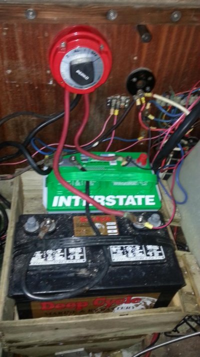
I have in mind to redo my electrical system, and to that end I have purchased the Add-a-Battery ACR (to replace the Perko) and the Promarine 12 amp dual-battery smart charger. I've taken the CPSS short electrical course and have read 2 marine electric books and spent hours and hours gleaning what I can from the Interwebs in relation to what and where to fuse, designing a new panel, sloppily sketching wiring diagrams imagining how my amazing new system will look and work.
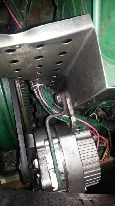
Until, of course, I venture out once again and climb up the ladder into the frozen boat to try to trace out the existing system of wires etc. One cable from Switch to Starter. Then a number of smallish wires running between the Alternator and the Starter, no idea what is which (even though I do have a version of the wiring diag. for the boat). So tempted to bail on rewiring the alternator circuit.
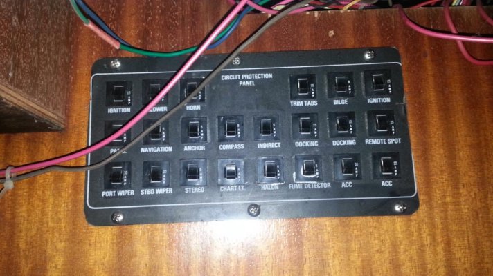
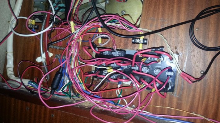
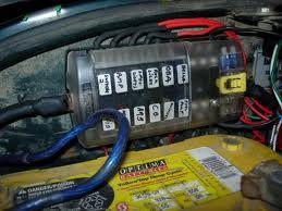
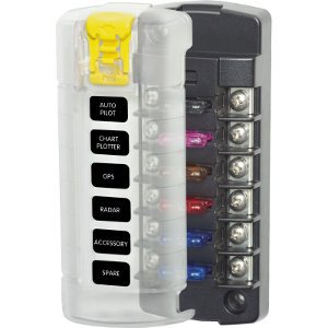
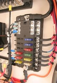
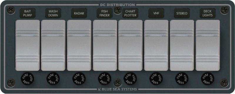
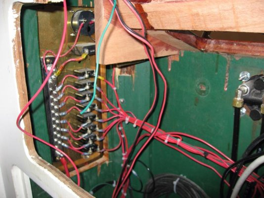
Also tempted to leave the existing engine instrument system in place for obvious reasons (i.e., too hard). So here are some pics of the existing panel, front and back, to explain my despair. I would like to replace it but not sure what folks do in terms of what items to group on each circuit - bilge pump. nav lights, 6 lights, 2 fans, VFH and depth, future 12 amp windlass, future wheel pilot, that's about it.