Murray,
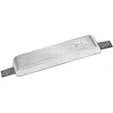
Take a run down to Rupert and get one of these. Perhaps that's what you meant by "streamlined" anode. I only have about 1" shaft showing ahead of the prop.
I think the experts say that the short nut should go on first and the larger "big" nut on top of the short nut. Seems bass akwards and I can't remember why .... hopefully someone else will help out. Has to do w the nut loading .. I think.
I'll bet fstbttms knows the real stuff.
I use the same thing prop zinc. I add some Loctite 242 (blue) to the allen head screw, as the tensile force holding it on goes away if you let it go to long. I think the new ones already have it on though.
I have posted this before on another electronic trawlering media...
")
The thin nut goes on first.
I spent 11 years wrenching on submarines. When I reflect back, I am still amazed at the amount of useful technical training that the Navy provided me. One of my favourite technical manuals to this day is NavShipsTechManual Chapter 75, Fasteners. I still use it all the time.
To quote:
075-5.3.4 JAM NUTS (LOCK NUTS). Jam nuts are an older variation of the prevailing torque concept. They are not usually recommended for new installations due to the tendency to use an improper thickness for the jam nut and to install them in the wrong relative positions.
075-5.3.4.1 Jam Nut Assembly. The jam nut assembly requires a regular or main nut and a thin jam nut, as shown in Figure 075-5-5. The assembly is installed with the thinner nut between the thick nut and the bearing surface. The main nut has to be as thick as if no jam nut were being used, because the main nut carries all the working load. The jam nut is usually about 2/3 as thick as the main nut. If the jam nut is too thin, however, the threads in the jam nut area will be damaged as the main nut will pull the bolt threads partially through the jam nut. Conversely, if the jam nut is too thick, the main nut cannot distort the threads enough.
075-5.3.4.2 Tightening the Jam Nut. At assembly, first tighten the jam nut to the same or slightly less percentage of the preload torque specified for the main nut, based on the relation the jam nut thickness bears to the thickness of the main nut. Then hold it in position with a wrench while you tighten the main nut. For example, if the jam nut is 2/3 as thick as the nut, tighten the jam nut to 1/2 to 2/3 of the torque used for the main nut. Then, when the main nut is tightened to the preload torque specified for the bolt, it stretches the bolt (stud), thereby tending to pull it through the jam nut. Any vibration or load that tends to loosen the bolted joint will allow the bolt to shrink back to its original length, leaving the jam nut tight against the main nut. This creates the necessary prevailing torque to prevent the jam or main nut assembly from rotating on the bolt.
Link to Chapter 75