Camera's and power requirements

The friendliest place on the web for anyone who enjoys boating.
If you have answers, please help by responding to the unanswered posts.

timjet

Guru
Joined
Apr 9, 2009
Messages
1,920
I just bought a pair of video camera's to monitor the engine room and the power requirements state: DC 12v/500mA max.
The units came with a 120v power adapter. Can I safely connect these units to my boats 12v power supply? I'm concerned about the 500mA max.

Tim
 
Typically the 500mA max means that is the max amp draw the device will use.
I'd put a 1 amp inline fuse in and go for it.
Also-
Your 12 volt system will vary from 12 +/- 14 volts and your camera specs may show a voltage range somewhere but I suspect you're fine.
 
Assuming you have an inverter aboard, it would be much better to plug in the AC adapter your cameras came with and let the adapter provide the managed, clean output the cameras will like. If you must do without the AC adapter, direct-connecting to the highly-variable 12v supply is not without risk (the cameras may well work ok initially but their working lives could be shortened significantly). Instead, find a DC-DC voltage regulator. These take in the wide range (11-14+ volts) of your DC supply and eliminate this variability, outputing a constant 12 (or often, 12.2) volts. Just select one that has a 1A max output (though you might find other devices you could connect to the output side that would also benefit from a 'clean' supply, like your chartplotter or heading sensor...in which case look for a higher A-output regulator). Anode is right...a 1A fuse for the cameras. DC-DC regulators can be bought very inexpensively (as little as $20-$30).
 
Tim, I just completed the install of two ER cameras last weekend and did exactly what you're describing. I had a home security system that had a failed DVR power supply. I trashed the DVR but kept the cameras.

Since they were 12V, I discarded the 110V wall wart and wired them through a 3 A fuse directly to a 12V power buss in my overhead panel. I wired the feeds through a 4-source video selector switch to my HDTV. I used low light cameras which give a surprisingly clear black and white display of the ER without ER lights. When I turn on the ER lights, they display in color.

I agree that the 500MA max on the wall wart is the max output of that power supply, not the max of the cameras. They will pull much less than that, but will only pull what they require. I don't even see mine on my battery monitor.
 
Tim, I also have a pair of cameras set up in my engine room as you describe. I have had no problems so far, but I do like Aquabelle's proposal of adding a DC-DC regulator. I did a quick Google search and only got step-up or step-down regulators. Can anyone point me in the right direction?
 
Your cameras are probably CMOS or possible CCD chips, both of which will utilize typically 3.3 V and/or 5 V at the circuit board/IC chip. There is probably a power converter (DC/DC) converter chip inside that is converting 12 V to 3.3 V and/or 5 V. These converters usually have a wide input voltage so you will probably be OK running them off normal boat 12 +2.3/-1 Volt power. You might be able to find the input voltage in the owners manual or on the manufacturers web site. If they are cheap cameras and you don't mind taking the risk, just connect one and use it for awhile see what happens. If it doesn't stop working hook up the other one.
 
Ok, thanks guys for all your input. I remember reading somewhere in the owners manual for my previously owned chartplotter and radar (the one Craig bought) that it should be turned off when the engines are started so they are not powered when the voltage is dropped due to engine start.
So maybe aquabelle has a point. Is a DC to DC voltage regulator just a large capacitor?
The cameras I have are Chinese cheap and cost about 40 bucs so I don't think they will last. But I just got a new chartplotter with a video feed so I gotta try it out. The ones from Garmin are $500 or so.

Flywright; you said you used a 4 source video selector switch. My Raymarine display will allow one camera input but if you want more you must buy a separate cable sold only my Raymarine to add additional cameras. I wonder if I can use a source video selector switch and connect it to my Raymarine display and not pay for their expensive cable?
 
Tim, the output from my cameras is via bnc connector. I used bnc to rca adapters to convert to the rca jack needed for the switch and hdtv. If your connectors are similar, I bet it would work for you.

I'll try to get some photos this weekend.
 
The cameras I have are Chinese cheap and cost about 40 bucs so I don't think they will last. But I just got a new chartplotter with a video feed so I gotta try it out. The ones from Garmin are $500 or so.


I ran " cheap " Chinese cameras on 12vdc for years on Volunteer and never had a issue regarding the clean constant power...
Wire them, fuse them, use them.
Good Luck
HOLLYWOOD
 
Here's a picture of my TV display from the ER cameras with Cspeudonym's spawn crawling around my ER.

This one is with the ER lights on:
img_154736_0_26d15f569549d34a57c4efff8f463e1a.jpg


This one is with all ER doors closed and ER lights off. It's so dark in there you can't see your hand in front of your face.

img_154736_1_6e80ed4fde959b975c63fcf97720dcab.jpg


This is the BNC-RCA adapter I used to convert between the 2 connector types.

img_154736_2_1384457f0647b3e914ad5556c901eb87.jpg


This is my audio/video control panel on my overhead.

img_154736_3_d971cb927e6f02a476402f0cfffe623f.jpg
 
This is my audio/video control panel on my overhead.
g[/IMG]
Very,very nice! II looks like you actually know what you're doing!
 
Kyle enjoyed your engine room as much as the Sherpa duties. He came home with a pocket full of electrical wires from your ER. Hope they weren't important?

:)
 
Here is a link to one type of voltage stabilizer per my post #3 above. This one takes a wide range of input voltages (8-40v) and outputs 12v and up to 6A. Others are available with various narrower input ranges and greater and lesser amp draw capacities. There are models available that output 5v and 3v also. Pretty readily available from computer component supply shops I think.

8V-40V to 12V 6A Max 72W DC-DC Step Down Converter Voltage Transformer F Vehicle | eBay
 
Flywright...your post at #11 shows a great-looking audio/video control panel. Can you talk us through what it does? Did you build it or buy it ready-configured?
 
Wireless cameras: anyone using a wireless camera in their engine room, picked up via a router and displayed on a laptop at the helm station? On longer passages I have a laptop at the lower helm and this is when I'd most value an engine room view....and not having to run cables has a lot of appeal !
 
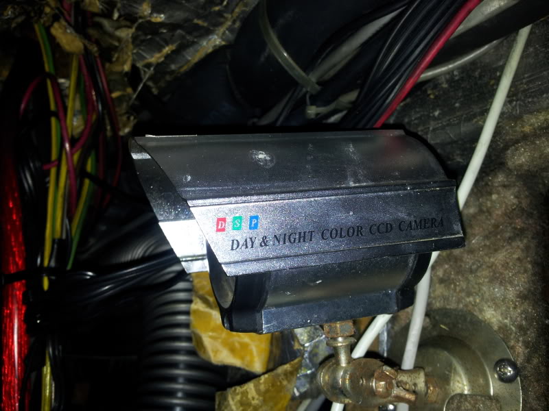
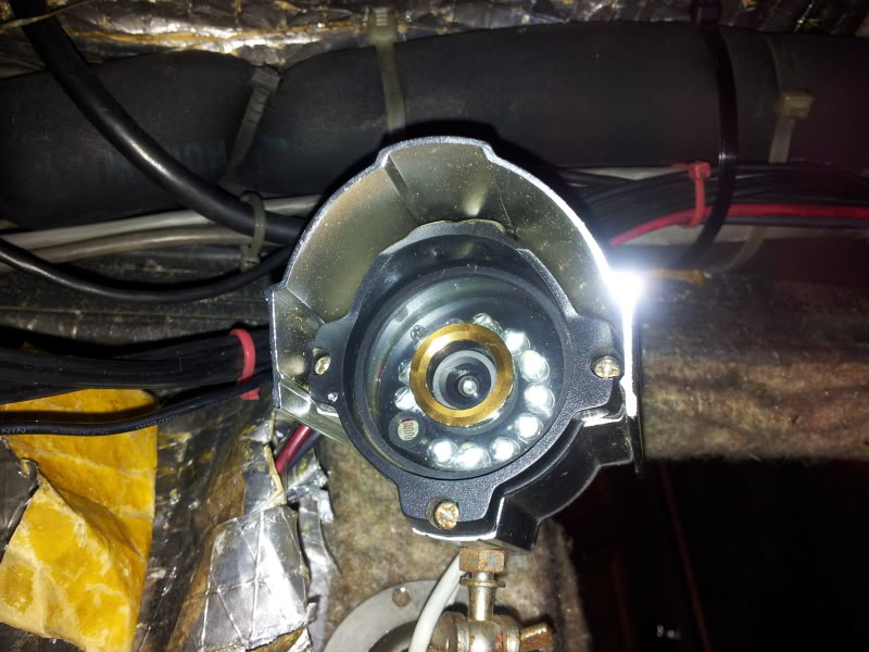
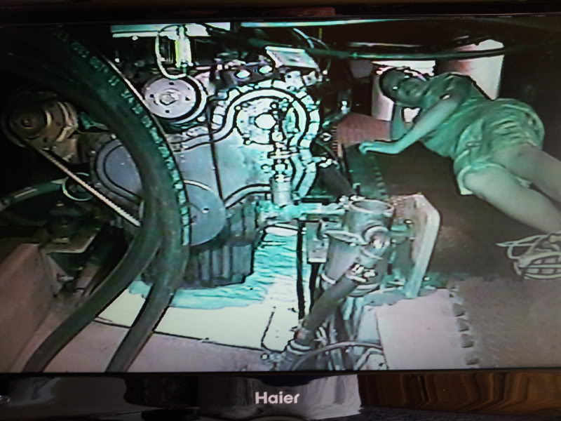
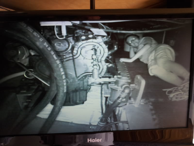
Tim, I don't have the camera specs, but they are just standard issue home security cameras from a system I bought years ago at Costco. Here are some pics...

img_154779_0_79615e3d26628b48bd43764763ada625.jpg


img_154779_1_04858728ec93bda7c7c7c9dd70dea476.jpg


Aquabelle, The panel was designed by me and manufactured by Front Panel Express. They have some very user-friendly design software that allowed me to lay out the panel as I needed it with materials, fonts, colors of my choosing. The total delivered cost in anodized aluminum was just under $70.

I'll post the panel pic again for easier reference...

img_154779_2_d971cb927e6f02a476402f0cfffe623f.jpg


The top left Power quadrant serve as on/off switches to the 3 listed items:
1. Video cameras,
2. Yandina Battery Combiner (It's actually a defeat switch that allows me to prevent the battery combining when on shore power and switch ON during engine alternator charging.), and
3. WIFI is power to my Rogue Wave WIFI Extender and a wireless router.

I struggled with including the Yandina switch in this panel b/c it really isn't audio, video or wifi, but included it b/c the switch matched the others and I had panel room. All three switches are normally down when closing up the boat.

The bottom left quadrant is contains the four blue camera selector push buttons. I'm only using 1 and 2 for the engines for now. I plan to add an aft-looking camera in the near future.

A 12V outlet is located in the center position and there is a Tunelink Bluetooth stereo interface unit inserted into the power outlet in the picture. This Tunelink module has a USB charge plug and an aux jack output.

The panel AUX jack connects directly to the stereo input for direct feed of MP3 music players or allows an aux feed via male-to male 3.5mm plug from the Tunelink.

The right section has 2 white speaker selector push buttons which allow me to select salon rear and/or flybridge speakers on the rear channel of the stereo. This combined with the stereo fader control gives us flexibility in selecting or deselecting interior and exterior speakers (with subwoofers) as needed.

All this is powered by the house 12V circuit without any problems so far.
 
Aquabelle, I have no experience with wireless cameras. I might be high tech, but I'm low budget. I like the idea of wireless, but to be honest, running wires on my boat is not that tough. In my experience, sometimes wireless works and when it does, it's great. But other times, it fails at the worst moments.

I like the bluetooth stereo connection 90% of the time, but sometimes, it just has a mind of its own and I have to start from scratch to reconnect.

When I get frustrated, I plug it into a wire and chill!!
 
. In my experience, sometimes wireless works and when it does, it's great. But other times, it fails at the worst moments.

That's been my experience too. If you really want it to work go wired.
 
With the discussion of DC-DC converters I think it would be a good idea to protect my chart plotter against voltage drops during engine start. I've noticed that if I have my chart plotter on and then start the engines, sometimes the chart plotter will turn off.

So to prevent this from happening should I use one of these: 8V 40V to 12V 6A Max 72W DC DC Step Down Converter Voltage Transformer F Vehicle | eBay

My plotter specs: Power consumption: 23 watts. This is 2 amps but the fuse requirement is 7 amp.

So would that unit be appropriate for this use?
 
Tim, sorry for the detour, but why do your electronics see a voltage drop? Are they powered by the start batts or are the start and house banks paralleled during start?

I run all my electronics on my house bank and my windlass on my start bank. My start and house banks are isolated from each other until the alternators start bringing the batts above 13.1V (+/-), then the combiner ties them. I never see a dropout of my electronics during start.
 
Tim: yes, that DC-DC converter/stabilizer will suit and should avoid the voltage sags you are seeing. You can spend more and get even more protection...take a look at the Newmar site & look at their power supply protection products,some of which even provide a back up/UPS battery. But I think the DC-DC converter is a great low-cost solution.

Having said that, Al at post #23 makes a good point: good practice is to have your Start and heavy-draw loads (davit, windlass, even thruster) on a Start bank and have electronics either on a small dedicated battery or (more commonly) on the House bank. Then your electronics are only exposed to heavy inverter loads on the House bank causing voltage sag....but again, the DC-DC converter/stabilizer will largely take care of that.
 
This is a link to the Newmar products that Aquabelle mentioned. They make very high quality products and stand behind them. I have a Newmar charger on my boat and it seems bullet proof.
 
Tim, sorry for the detour, but why do your electronics see a voltage drop? Are they powered by the start batts or are the start and house banks paralleled during start?

Good question Al. My DC power is set up in two banks with the house consisting of 5 AGM's and the Start consisiting of one AGM. I cannot isolate the banks except thru the battery switch. The position of the battery switch either 1 or 2 or Both powers everything.

The battery switch is almost always in the Both position except when at anchor when I switch to the House position.

I haven't thought of installing a combiner and or isolator, but this would be a good reason. But like Aquabella said perhaps just adding a cheap DC-DC converter would accomplish the same thing at a much cheaper cost, at least for the electronics. Are there other good reasons to consider a combiner or isolator?

I am curious as to why the chart plotter manual states a requirement of a 7 amp fuse but only draws 23 watts (2 amp).
 
Tim: yes, that DC-DC converter/stabilizer will suit and should avoid the voltage sags you are seeing. But I think the DC-DC converter is a great low-cost solution.

Without getting into an engineering explanation can these cheap DC-DC converters supply a constant 12v after the supply voltage has dropped for several seconds or are we talking about milliseconds? And how far below 12v can the supply voltage drop and these things still keep putting out 12v?
 
Good question Al. My DC power is set up in two banks with the house consisting of 5 AGM's and the Start consisiting of one AGM. I cannot isolate the banks except thru the battery switch. The position of the battery switch either 1 or 2 or Both powers everything.

The battery switch is almost always in the Both position except when at anchor when I switch to the House position.

I haven't thought of installing a combiner and or isolator, but this would be a good reason. But like Aquabella said perhaps just adding a cheap DC-DC converter would accomplish the same thing at a much cheaper cost, at least for the electronics. Are there other good reasons to consider a combiner or isolator?

I am curious as to why the chart plotter manual states a requirement of a 7 amp fuse but only draws 23 watts (2 amp).

Tim, when I recabled my boat, I wired the alternator charge output directly to the battery banks so that any load switching done at the battery switches would not affect the charging. So the batt switches control LOAD only. Then I added the combiner to allow automatic combining of the banks while charging underway. I never have to touch my battery switches unless I need to remove load immediately, like in the event of a fire. For that reason, I located the switches outside of the ER door.

I defeat the auto combiner with the OFF switch while charging in the slip so that the multi-bank charger can provide what each battery needs rather than treat them like a single bank. I normally throw the Combiner toggle switch to ON when I'm underway so the output of both alternators can be utilized to recharge the house bank more quickly. If I forget to turn it off when I drop anchor again and shut down the engines, no problem...the combiner automatically isolates the banks when the alternator charge goes away so the loads on the house are isolated from the start battery.

It's an automatic way to keep the loads isolated but still be able to take advantage of the charge from both alternators when underway.
 
Thanks Al. My alternator 1 goes to house and alternator 2 to start. I think when the battery switch is in the Both position the charging part of my DC system remains isolated because I read slightly different voltages on the helm volt meters.
I see the advantages of your setup. Ball park what is a system as you describe cost?

Back to the cameras; do I keep the ferrite located on the power cord?
 
My Yandina combiner was under $100, but if I were to do it today, I'd go with the Blue Sea ACR for about $60 more. Cables from alternators to batts (instead of using the starter cables as many manufacturers do) under $100...maybe $75?? Most else is just rearranging what I had except for a little switch here or some connectors there...just incidentals.

I tossed the ferrite module and see no interference.
 

Latest posts

Back
Top Bottom