GFI outlets?

The friendliest place on the web for anyone who enjoys boating.
If you have answers, please help by responding to the unanswered posts.
Status
Not open for further replies.
The boat should have the appropriate lock outs so that can't happen, so there is only one source of power to a circuit. .
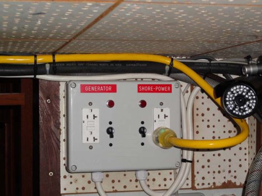
A transfer switch should take care of this but it has to transfer all three conductors including the ground.

Unplugging the shorepower cord does the same thing, but as I posted above, there's a good chance of this not happening due to human error.
 
Our boat has three AC outlet circuits, port, center, and starboard. All the AC putlets are the standard double receptical configuration.

The center circuit only has one outlet on it and that's in the engine room. The port outlet has two, one in the galley and one in the aft cabin. The starboard circuit has four, one in the forward cabin, one in the main cabin, one in the aft head, and one in the aft cabin.

Three of the outlets are GFI. The one on the starboard side of the main cabin, the one in the aft head (starboard), and the port outlet in the aft cabin. We have a GFI tester. In the circuit with two GFI outlets, tripping one outlet does not trip the other GFI outlet or the circuit itself. It just kills the power in the one outlet.

The easy way to fix this is to replace all the non-GFCI receptacles with GFCI receptacles. The other way (not necessarily better) is to change the wiring so the existing receptacles protect the others. You may have to move them around.

Considering the low cost of GFCI receptacles and the electrical knowledge needed to rearrange the wiring, replacing the non-GFCI receptacles with GFCI receptacles seems the better way.
 
Fix what? There isn't a problem. We don't want the other outlets in the circuit to lose power, only the GFI outlet that gets tripped. That's how the system in our boat works now.
 
This is what the manuel for my Xantrex Prosine inverter says.

Neutral Grounding:
a) 120V models: The neutral conductor of the AC
output circuit of the Prosine Inverter is
automatically connected to the safety ground during
inverter operation. This conforms to National
Electrical Code requirements that separately
derived AC sources (such as inverters and
generators) have their neutral conductors tied to
ground in the same way that the neutral conductor
from the utility is tied to ground at the AC breaker
panel. For models configured with a transfer relay,
when AC utility power is present and the Prosine
Inverter is in bypass mode, this connection (neutral
of the inverter‘s AC output to input safety ground)
is not present so that the utility neutral is only
connected to ground at your breaker panel, as
required.
b) 230V models: There is no connection made inside
the Prosine Inverter from either of the line
conductors (line or neutral) to the safety ground.
2.4.3 Ground Fault Circuit Interrupters
(GFCIs)
Installations in Recreational Vehicles (for North
American approvals) will require GFCI protection of
all branch circuits connected to the AC output of the
hardwire terminal equipped Prosine Inverters. In
addition, electrical codes require GFCI protection of
certain receptacles in residential installations. While
the true sine wave output of the Prosine Inverter is
equivalent to the waveform provided by utilities,
compliance with UL standards requires us to test and
recommend specific GFCIs.
 
Fix what? There isn't a problem. We don't want the other outlets in the circuit to lose power, only the GFI outlet that gets tripped. That's how the system in our boat works now.

If you don't want to 'fix" it, why did you bother posting it at all?

My house is like that, some GFCI protected, some not. I didn't think it was worthy of a post.
 
People were asking about the use of GFIs on boats so I simply described what our system is like in the event someone might find the description useful to what they're trying to do. I wasn't asking for a solution to a problem because we don't have one.
 
People were asking about the use of GFIs on boats so I simply described what our system is like. I wasn't asking for a solution to a problem because we don't have one.

If you had said that, it would have saved me a lot of typing.

On the other hand, some folks may want to increase their electrical safety by protecting all the receptacles. Now they know how.

I believe that was part of the original poster's question.
 
If you had said that, it would have saved me a lot of typing.

.

If you choose to answer a question that was never asked you've got no one to blame but yourself for the typing effort.

Other posters seemed to be saying that tripping a GFI outlet will cause other GFI outlets on the same circuit to trip as well as though it was an "always the case" situation. This is not the case on our boat which is one reason I posted our system's description.
 
Last edited:
If you had said that, it would have saved me a lot of typing.

??????? I think you're wrong, Ron. I reread these posts 3 times and never came to the conclusion that Marin was stating a problem. :confused:
 
If you (and any worker, mechanic or future owner) never runs the genset or inverter while the shorepower cord is still connected there won't be a problem, but safety standards and codes are designed to protect against human error.

We run shore power and a generator in parallel everytime we arrive or depart. It is called "seamless transfer" and is as common as house electricians giving bad advice to boat owners.

Doing that is not "human error" it is common practice and for the most part, completely automatic.
 
Fix what? There isn't a problem. We don't want the other outlets in the circuit to lose power, only the GFI outlet that gets tripped. That's how the system in our boat works now.

So, you are on a boat (right?). There is absolutely positively NO chance that nothing you will ever plug in to one of those non protected outlets will ever get water on it or around it? Really? Continued good fortune to you!
 
We run shore power and a generator in parallel everytime we arrive or depart. It is called "seamless transfer" and is as common as house electricians giving bad advice to boat owners.

Doing that is not "human error" it is common practice and for the most part, completely automatic.

Really? Both providing power to the same circuit? I think not. You are certainly NOT following the proper practice for boats. It is not uncommon to have one running one set of circuits and another a different one. So tell me what does your AC panel look like?

And Marin, you DO have a problem.. see the third part of my tag line.
 
And Marin, you DO have a problem.. see the third part of my tag line.

I didn't build the boat. American Marine did. And they and their successor Grand Banks Llc. built thousands of them. Just like ours. And most of them don't have ANY GFI outlets in them. And I have yet to hear of anyone having a problem as a result.

Our boat had no GFI outlets when we bought it, just like the majority of Grand Banks boats when they were built. At the suggestion of a surveyor during an insurance survey we changed the outlet in the aft head, which also contains the shower, to a GFI. Later we changed over two more due to their location and potential--- a very, very remote potential--- for a problem.

Next time you cross a street, think very, very carefully before you step off the curb. Because there's a chance that you will be killed. I put that in the same category as your earlier post.:)
 
<H1>T.S. Patriot State Engineering Manual</H1>Patriot State was the training ship of the Massachusetts Maritime Academy from 1986 to 1998.

Shifting from Shore Power to Ship's Power


  1. The ship's auxiliary plant will be started and one turbo generator brought up to speed. When the generator is ready in all respects, first check the amperage being drawn on the shore power ammeter. If the load is in excess of 600 amps, strip equipment off the board until the load is reduced. Selectively start with white handled (non vital) switches.
  2. Parallel the generator with shore power by using the manual voltage regulator and matching voltages. Control the synchroscope until it is slowly rotating clockwise. Check the synchronizing lights and have the cycles at 60+. As the synchroscope slowly rotates clockwise, close the generator circuit breaker at the "11 o'clock" position.
  3. Put the voltage regulator in "auto" and increase the load on the ship's generator until it is taking approximately the same amperage as the shore power.
  4. Open the ship's shore power breaker and tag it. Stabilize plant operation. NOTE: The shore power cable can be left connected and energized to be available if needed up until a few hours of getting underway.
  5. When the plant has stabilized and the shore power cable is to be removed, the shore power breaker on the dock is opened and tagged. At Buzzards Bay, Facilities personnel have the keys to the building where the breaker is located.
  6. At this point, test for voltage on all phases in the ship's shore power cabling, connection box to insure that there is no voltage.
  7. Disconnect the shore power cables from the ship's shore power connection box and coil the cables on the rack ashore. Wrap conductor ends to make them weather tight. Replace the ship's connection box cover and store all tools.
  8. Set up the emergency diesel generator by turning the start switch to "on" (no. 9, 120 vdc panel).
 
For most of us with 30-65ft boats , we CAN live without electric for 60 seconds.

While a transfer switch may work , if wired properly , even automatically , its just more to buy install and maintain.

Weather it melts down when a boat on dock power with you starts his noisemaker is always open to speculation.

For 50A 250V or less , the solution is cheap simple and safe.

Install a plug inside that is the boat power supply , and plug it into a socket.

Shore Power , Generator 1, Night Generator, Inverter,Engine Cruise gen power , what ever is installed.

The neutral/ ground question will no longer be a problem, as each should be grounded at its source.

So simple a guest could do it.
 
So tell me what does your AC panel look like?

Here is a typical board. It primarily provides generator control with load sharing and shedding with a DC distribution subpanel on the side. An alarm and monitoring system is also incorporated in the board in a normal installation.

Circuit protection and isolation grunt work is done by subpanels near the consumers. Because even on the largest yachts there is seldom room for centralized power management, fairly comprehensive distribution panels are located in areas where the power is used.

When you want to start a generator and parallel it with shore power, you push the green button.
 

Attachments

  • switch_board.jpg
    switch_board.jpg
    78.8 KB · Views: 78
Weather it melts down when a boat on dock power with you starts his noisemaker is always open to speculation.

Describe the mechanism by which a transfer switch on Boat A would "melt down" because the generator on Boat B was started. Please.
 
For most of us with 30-65ft boats , we CAN live without electric for 60 seconds.

While a transfer switch may work , if wired properly , even automatically , its just more to buy install and maintain.

Weather it melts down when a boat on dock power with you starts his noisemaker is always open to speculation.

For 50A 250V or less , the solution is cheap simple and safe.

Install a plug inside that is the boat power supply , and plug it into a socket.

Shore Power , Generator 1, Night Generator, Inverter,Engine Cruise gen power , what ever is installed.

The neutral/ ground question will no longer be a problem, as each should be grounded at its source.

So simple a guest could do it.

That will certainly work. It's not as convenient as throwing a switch or having an automatic transfer switch on the genset or inverter, but it will work just fine.
 
For most of us with 30-65ft boats , we CAN live without electric for 60 seconds.

While a transfer switch may work , if wired properly , even automatically , its just more to buy install and maintain.

Weather it melts down when a boat on dock power with you starts his noisemaker is always open to speculation.

For 50A 250V or less , the solution is cheap simple and safe.

Install a plug inside that is the boat power supply , and plug it into a socket.

Shore Power , Generator 1, Night Generator, Inverter,Engine Cruise gen power , what ever is installed.

The neutral/ ground question will no longer be a problem, as each should be grounded at its source.

So simple a guest could do it.

I have similar arrangement that supplies my watermaker or dive compressor. The ac electrical system on my boat is somewhat antequated and I made this to ensure I don't overload it.
 

Attachments

  • Outlets.jpg
    Outlets.jpg
    79.8 KB · Views: 103
I have similar arrangement that supplies my watermaker or dive compressor. The ac electrical system on my boat is somewhat antequated and I made this to ensure I don't overload it.


Assuming you didn't connect the green wires together or to the box, that should work just fine with no chance of human error. It also provides for easily disconnecting all power for when you want to service your electrical system.
 
Status
Not open for further replies.

Latest posts

Back
Top Bottom