GFI outlets?

The friendliest place on the web for anyone who enjoys boating.
If you have answers, please help by responding to the unanswered posts.
Status
Not open for further replies.

Restitution

Senior Member
Joined
Mar 12, 2012
Messages
201
Location
USA
Vessel Name
"Restitution"
Vessel Make
38' Californian
I purchased RESTITUTION a year ago. Have old school outlets on board. Thety are three prong. Should I replace ALL with GFI's or does one per circuit work?

Also, Genset has a green wire that is 3rd utility ground and NOT connected to anything. It is just a four inch wire coming off of the genset going to nothing. How should I wire this up properly to get a good utility ground to the 110 panel and all outlets?
 
One GFI per circuit should do it. I will not venture an opinion on the green wire on the generator.
 
Greetings,
Mr. Sam. I agree with Mr. Moonstruck. One GFCI per circuit will work but I think it depends on WHERE in the circuit the GFCI is. Beginning or end, I can't remember. More than one per circuit may have you chasing "trips" all over the boat and on our boat, shore power interruption requires resetting the GFCI. Bad enough with one but several? You would get tired of the process VERY quickly.
 
The green & white need to be bonded at the generator while the gennie is running and unbonded while on shore power.
 
I purchased RESTITUTION a year ago. Have old school outlets on board. Thety are three prong. Should I replace ALL with GFI's or does one per circuit work?

A GFI if placed in a string of plugs, if wired properly will protect the complete string. The instructions are in the box with the GFI.
 
Last edited by a moderator:
Greetings,
Mr. Sam. I agree with Mr. Moonstruck. One GFCI per circuit will work but I think it depends on WHERE in the circuit the GFCI is. Beginning or end, I can't remember.

Ans: At the beginning.
 
The green & white need to be bonded at the generator while the gennie is running and unbonded while on shore power.

A lot of people don't know this, but it is correct. We would hope the transfer switch would take care of this, but if you're not sure, call in a qualified marine electrician.
 
A single GFCI receptacle can be placed at the first outlet in a circuit and can be wiared to protect all the outlets downstream of that outlet.

Anywhere else and it only protects itself and any outlets downstream.

Again, you might want to call in a qualified marine electrician just so you're comfortable that your boat is wired safely. Electricity and water can be a fatal mix if not done correctly.
 
You can find the outlets on the circuit by turning off the breaker and checking by plugging in a light to find the dead outlets. You can find the first outlet by turning off the breaker, remove the outlet that you think is first, then check the other outlets to see if they are dead. If it is not the right outlet, then it is the same procedure by the process of elimination.

Oh yeah, don't forget to turn the breaker back on for the testing stage.
 
You can find the outlets on the circuit by turning off the breaker and checking by plugging in a light ..............

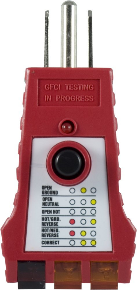
Better than a light, home centers and electrical supply houses sell a plug-in tester that shows if a receptical has power, if it's wired correctly, and has a button to test the GFCI feature. About $10.00.
 
Last edited:
There is another possibility, and that is that your boat has ground fault breaker or breakers at the head of each major circuit. That's how Hatteras did it, and the fact that you have no GFCI outlets on your boat makes that possibility a real one. Got a picture of your panel(s)?

A big issue on older boats is figuring out what various prior owners did to the electrical system in terms of additions and deletions. To break out a panel for my inverter, I had to eliminate one of the master ground fault breakers that fed a particular circuit. So I installed a GFCI outlet right at the panel where I KNEW it would be first in line. Turned out it's come in handy otherwise. As a belt and suspenders move you can always put GFCI's in the usual suspect places like galleys and heads, but on a boat that is not the sole answer, all outlets need to be protected; I have had my GFCI circuits "tested" a few times by various items like work lights, buffers, extension cords etc finding their way into water.

I agree with Ron. AC is not something to be trifled with. Get some qualified eyes on the situation if you have any doubts whatsoever. I am very comfortable with electrical work but almost always get a "real" marine electrician to help or at least consult with the high voltage stuff.

No comment on the generator wire, there are too many variables, so without seeing the whole boat any postulation would be irresponsible.
 
Last edited:
There is another possibility, and that is that your boat has ground fault breaker or breakers at the head of each major circuit. That's how Hatteras did it, and the fact that you have no GFCI outlets on your boat makes that possibility a real one. .

That's where the tester I mentioned above comes in handy. The guy who surveyed my boat had one. I have one also.

51TKrVQ28fL._SL1000_.jpg

Amazon.com: GE 50957 GFCI Tester for Proper Installation/Operation 110-125V: Home Improvement
 
A lot of people don't know this, but it is correct. We would hope the transfer switch would take care of this, but if you're not sure, call in a qualified marine electrician.

More house electrician nonsense.

It is house electrician nonsense because it is based on terrestrial electrical code rules that state a neutral will only be bonded to ground at a single location.

Unless you have a houseboat that is firmly fixed to the beach and has street address on the side instead of a hailing port you should adhere to marine practice and forget what house electricians tell you "must" be done.

Thank you for your kind words. :rolleyes:

Bob and I are still correct even if the NEC does not apply. Electricity does not care if it's on a boat.
 
Last edited:
That tester will tell you if an outlet is working and/or has a fault; but it won't tell if the outlet is first in the circuit.

Actually, you can find this out pretty fast by using the tester in each outlet and seeing which GFCI pops.

Scott Welch
Island Eagle
 
That tester will tell you if an outlet is working and/or has a fault; but it won't tell if the outlet is first in the circuit.


That's correct and I didn't mean to imply that it would, just that it's a good way to check GFCI receptacles and/or breakers.

Note: It's possible that there will be no "first" outlet in a circuit. The circuit could branch before any outlets.
 
"call in a qualified marine electrician "

Where does one find such an individual? In our area, Galveston Bay/Clear Lake, TX, I have yet to run across any marine tradesman worth a damn.

Bob
 
More house electrician nonsense.

It is house electrician nonsense because it is based on terrestrial electrical code rules that state a neutral will only be bonded to ground at a single location.

Unless you have a houseboat that is firmly fixed to the beach and has street address on the side instead of a hailing port you should adhere to marine practice and forget what house electricians tell you "must" be done.

Not only this this wrong, but it's wrong in a way that can kill you.

There is a very good reason for a single neutral bonding point, which I will describe: Current in your AC system flows through two wires: the hot and the neutral. The ground wire exists so that if there is a any "leakage" of electrons, they will flow to the ground and that will trip any over-current protection device (OCPD, typically a breaker or fuse), which is located in the same circuit as the OCPD.

Now, I want you to imagine that you have the ground bonded to the neutral in two locations, for example the shore power breaker panel on the dock and also the genset. Now imagine that for some reason the ground connection from the shore panel breaker to the boat is poor -- which can easily happen for any number of reasons: a bad connection in the cable, a wiring problem on the dock, a wiring problem on the boat, etc. Now imaging that we have the same leakage of electrons from the hot to the ground on the boat. This will not induce any current flow from hot to ground in the OCPD. In fact, even worse, since there is a second connection to groundon the boat, this will have the effect of energizing the ground circuit on the boat to the full potential of the hot leg of the incoming circuit. This is potentially lethal to both people on your boat as well as to people on other boats and in the water.

If you want some gruesome reading, Google "electrocution at the dock ground bonding". And here's a link to proper "marine practice", from Steve D'Antonio, that directly contradicts the advice given by the poster quoted above: Steve D'Antonio - Marine Consulting Services for Boat Buyers, Boat Owners, and Manufacturers

Scott Welch
Island Eagle
 
Tell it to the folks who might know a bit more about marine generators than the average house electrician...


"There is no consensus of opinion on whether the neutral conductor should be connected to the bonding system (grounded) or not (floating ground).

Grounding the neutral may increase electrolytic corrosion. Not grounding the neutral creates a potential shock hazard. The American Boat and Yacht Council recommends grounding the neutral at the generator for safety reasons, though this may shorten the life of heat exchangers and other components. Northern Lights heartily recommends grounding the neutral since personal safety takes priority over all other considerations.

For additional electrical information, consult the AC wiring diagrams in the Generator Manual for the generator end installed on your set."
 
Actually, you can find this out pretty fast by using the tester in each outlet and seeing which GFCI pops.

Scott Welch
Island Eagle

Scot, you are correct if the circuit is already GFI protected. The OP was looking to add GFIs because his boat has none. He would either have to have a GFI breaker in his panel or find the first outlet to protect the circuit.
 
My original post said to bond the ground and neutral while the noisemaker was running and lift the bond when its not running. It seems ABYC and Northern Lights at a minimum agree with me. I can live with company like that whether or not any other resident experts agree with me.
 
Again, there is a reason why without seeing how the boat is actually wired, making advisory statements is irresponsible. We don't know to what extent some PO modified things for better or worse, what the hwole picture looks like.

By the way, here is the ABYC standard... and the variations that one must need to know:

11.5.3.2. A grounded neutral system is required.
The neutral for AC power sources shall be grounded
only at the following points:
11.5.3.2.1. The shore power neutral is
grounded through the shore power cable and shall not
be grounded on board the boat.
11.5.3.2.2. The secondary neutral of an
isolation transformer or polarization transformer shall
be grounded at the secondary of an isolation or
polarization transformer.

11.5.3.2.3. The generator neutral shall be
grounded at the generator. (See DIAGRAM 2 or
DIAGRAM 4.)
11.5.3.2.4. The inverter output neutral shall
be grounded at the inverter. The inverter output
neutral shall be disconnected from ground when the
inverter is operating in the charger or the feed-through
mode(s). (See ABYC A-25, Power Inverters.)
EXCEPTION: Exception to E-11.5.3.2.2., E-
11.5.3.2.3 and E-11.5.3.2.4: For systems using an
isolation transformer or polarization transformer,
both the generator or inverter neutral and the
transformer secondary neutrals may be grounded at
the AC main grounding bus instead of at the
generator, inverter, or transformer secondaries. (See Diagram 5)

11.5.3.3. The main AC system grounding bus shall be connected to
11.5.3.3.1. the engine negative terminal or the DC main negative bus on grounded DC systems,
11.5.3.3.2. the boat’s DC grounding bus in
1installations using ungrounded DC electrical systems.

Note that they also require any household appliances that have a neutral/ground bonding strap to have that strap disconnected (note to 11.17.3.2.)

The thought that "electricity doesn't know if it is on a boat" is a dangerous one.
 
"call in a qualified marine electrician "

Where does one find such an individual? In our area, Galveston Bay/Clear Lake, TX, I have yet to run across any marine tradesman worth a damn.

Bob

Ask around. There is a very large commercial presence there of USCG inspected boats, so there are going to be plenty of qualified electricians. One place to start might be one of the commercial electronics suppliers, like Radio Holland, see if they can refer you. Or one of the local surveyors.
 
Again, there is a reason why without seeing how the boat is actually wired, making advisory statements is irresponsible.

As long as the statement is polite and "nice" it doesn't matter if it is irresponsible, wrong, or even dangerous. That is an official forum rule.


The thought that "electricity doesn't know if it is on a boat" is a dangerous one.

See above. :)
 
Some place on the boat the zinc loop green wire, should be connected to the AC 110 ground already, so at the outlet its already grounded. When at dock the AC 110 ground, green wire, is the ground and when away from the dock the zinc loop, green wire, is the ground. Might want to have a marine electrician check to make sure? So there is not need to connect the gen set green wire.

It is recommend that all outlets close to s sink and outside should have a GFI. Actually you can buy a plug in GFI at Lowes/home that meets the requirements. :thumb:
 
Tell it to the folks who might know a bit more about marine generators than the average house electrician...


"There is no consensus of opinion on whether the neutral conductor should be connected to the bonding system (grounded) or not (floating ground).

Grounding the neutral may increase electrolytic corrosion. Not grounding the neutral creates a potential shock hazard. The American Boat and Yacht Council recommends grounding the neutral at the generator for safety reasons, though this may shorten the life of heat exchangers and other components. Northern Lights heartily recommends grounding the neutral since personal safety takes priority over all other considerations.

For additional electrical information, consult the AC wiring diagrams in the Generator Manual for the generator end installed on your set."

The neutral and ground should be connected together at the genset (or inverter) when one of these is supplying power. At the same time, the ground connection to shore power must be broken or there will be two grounds, a dangerous and non-code situation.

If you (and any worker, mechanic or future owner) never runs the genset or inverter while the shorepower cord is still connected there won't be a problem, but safety standards and codes are designed to protect against human error.

The boat should have the appropriate lock outs so that can't happen, so there is only one source of power to a circuit. Better yet, isolation transformers eliminate this issue vis shorepower.

This does bring up something that I have not thought through: Some inverter manufacturers such as Victron and Mastervolt tout the ability of their inverters to add to a generator's or even shore power output in case of over load. What do they do to accomplish this safely (which I am sure they do, great companies). Again, to quote ABYC:

11.5.3.7. Individual circuits shall not be capable of being energized by more than one source of electrical power at a time. Each shore power inlet, generator, or inverter is a separate source of electrical power.
11.5.3.7.1. The transfer from one power source circuit to another shall be made by a means that opens all current-carrying conductors, including neutrals, before closing the alternate source circuit, and prevents arc-over between sources.
 
This does bring up something that I have not thought through: Some inverter manufacturers such as Victron and Mastervolt tout the ability of their inverters to add to a generator's or even shore power output in case of over load. What do they do to accomplish this safely (which I am sure they do, great companies).

This is an excellent question. I have a Trace/Xatrex SW4024MC, and it does not meet this requirement. In fact, all in the 4024 all three neutrals (shore, genset, inverter) are permanently bonded in the inverter. I sort of get around the problem by using an isolation transformer and making that the sold neutral bond, but that's a pretty poor solution. I talked to an engineer at Xantrex about the problem, and they basically said "Yep, it's a problem alright. Too bad."

There's a very good article about the problem here, well worth reading: Our Odyssey-Automatic Transfer Switch

Scot Welch
Island Eagle
 
Our boat has three AC outlet circuits, port, center, and starboard. All the AC putlets are the standard double receptical configuration.

The center circuit only has one outlet on it and that's in the engine room. The port outlet has two, one in the galley and one in the aft cabin. The starboard circuit has four, one in the forward cabin, one in the main cabin, one in the aft head, and one in the aft cabin.

Three of the outlets are GFI. The one on the starboard side of the main cabin, the one in the aft head (starboard), and the port outlet in the aft cabin. We have a GFI tester. In the circuit with two GFI outlets, tripping one outlet does not trip the other GFI outlet or the circuit itself. It just kills the power in the one outlet.

With regards to our generator (Onan 7.5 kw MDJE) the Onan rotary AC control switch has four positions. The two right side positions are shorepower available and shorepower connected to the AC breakers. The two left side positions are generator power available and generator power connected to the AC breakers.

This would seem to make it physically impossible for the AC circuits to be connected to both groundpower and generator power at the same time even if the generator was running at the dock with the groundpower cable connected.
 
Last edited:
Status
Not open for further replies.

Latest posts

Back
Top Bottom