Capn Chuck
Guru
- Joined
- Jan 20, 2009
- Messages
- 897
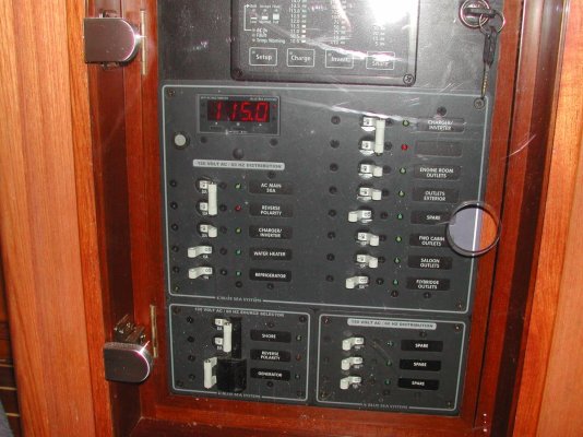
I'm ready to install my generator, so now I need to find a three way switch that will allow me to switch between the generator, shore power, and inverter. Here's the rub. The shore power connects to two panels via two separate power cords. The generator will need to connect to both panels. One is dedicated to the Air Conditioner. The inverter only connects to one panel. Anyone else have this set up and what is your solution? I'm thinking I may need two separate transfer switches. Chuck