hobbystuff
Senior Member
I am looking for some information regarding the shaft setup in my Universal 36 Tri-Cabin.
Currently I have a 1.75" Aquamet 22 shaft, driven by a 120 Lehman, the shaft was installed last year prior to the season, the new shaft was installed exactly as the old one.
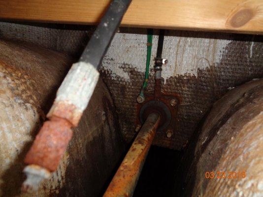
There is one cutlass bearing at the stern tube (which was also just replaced), the overall shaft length from stern tube to transmission flange is 130 inches. The shaft exits the tube at a cross-member that is ~ 60" back from the transmission coupling. A PSS shaft seal is mounted at that location. During discussion with the shaft supplier, he mentioned that this is a fairly long unsupported length, but that at our engine rating/rpm it "should" work out fine. My mechanic at the time convinced me of the same.
The boat has run just fine, although I feel like it could run smoother. Occasionally I think the shaft may experience a bit of "whip" at certain, low RPM settings.
This winter I am pulling the boat for several months so that I can do a rebuild on the Lehman. I am using a new mechanic, and during discussions he suggested we may want to take the time to install a cutlass bearing at the PSS seal to provide some additional shaft support. I have some questions:
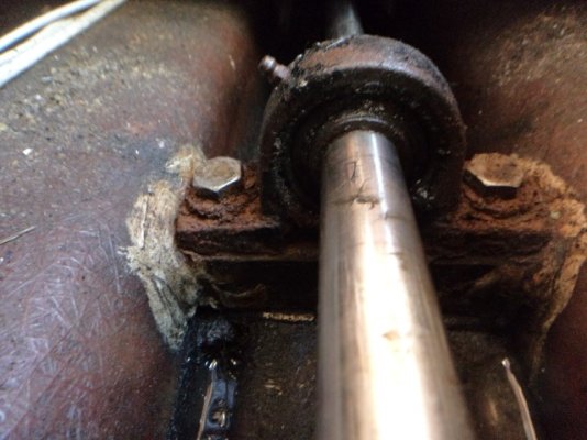
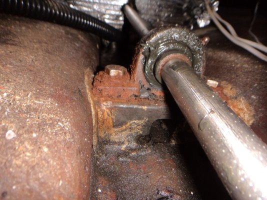
(1) I have no idea what the original stuffing box arrangement looked like on this boat, since the PSS was installed before I acquired it. Where the shaft exits the cross-member, there is a brass tube with a bolted flange that looks as if the threads were turned down to allow the PSS to slide on. While there is considerable clearance for the shaft in the shaft tube itself, this brass tube narrows the exit to about ~1/4" clearance around the shaft. This leads me to believe that in the original configuration, the stuffing box was located at this point and provided some additional shaft support.
(2) I am considering fabricating a new component that would allow me to install a cutlass bearing at this location, which would reduce the unsupported shaft length from 130" to 60" (transmission to PSS), and 70" (PSS to Shaft Log). My new mechanic seems to think this would be a nice improvement.
Long winded, I know. Any thoughts on this? What I don't want to do is go to all the work, and then find out I just made things worse.....
Thanks in advance.
Currently I have a 1.75" Aquamet 22 shaft, driven by a 120 Lehman, the shaft was installed last year prior to the season, the new shaft was installed exactly as the old one.
There is one cutlass bearing at the stern tube (which was also just replaced), the overall shaft length from stern tube to transmission flange is 130 inches. The shaft exits the tube at a cross-member that is ~ 60" back from the transmission coupling. A PSS shaft seal is mounted at that location. During discussion with the shaft supplier, he mentioned that this is a fairly long unsupported length, but that at our engine rating/rpm it "should" work out fine. My mechanic at the time convinced me of the same.
The boat has run just fine, although I feel like it could run smoother. Occasionally I think the shaft may experience a bit of "whip" at certain, low RPM settings.
This winter I am pulling the boat for several months so that I can do a rebuild on the Lehman. I am using a new mechanic, and during discussions he suggested we may want to take the time to install a cutlass bearing at the PSS seal to provide some additional shaft support. I have some questions:
(1) I have no idea what the original stuffing box arrangement looked like on this boat, since the PSS was installed before I acquired it. Where the shaft exits the cross-member, there is a brass tube with a bolted flange that looks as if the threads were turned down to allow the PSS to slide on. While there is considerable clearance for the shaft in the shaft tube itself, this brass tube narrows the exit to about ~1/4" clearance around the shaft. This leads me to believe that in the original configuration, the stuffing box was located at this point and provided some additional shaft support.
(2) I am considering fabricating a new component that would allow me to install a cutlass bearing at this location, which would reduce the unsupported shaft length from 130" to 60" (transmission to PSS), and 70" (PSS to Shaft Log). My new mechanic seems to think this would be a nice improvement.
Long winded, I know. Any thoughts on this? What I don't want to do is go to all the work, and then find out I just made things worse.....
Thanks in advance.


")