Please identify this fitting

The friendliest place on the web for anyone who enjoys boating.
If you have answers, please help by responding to the unanswered posts.

JDCAVE

Guru
Joined
Apr 3, 2011
Messages
2,903
Location
Canada
Vessel Name
Phoenix Hunter
Vessel Make
Kadey Krogen 42 (1985)
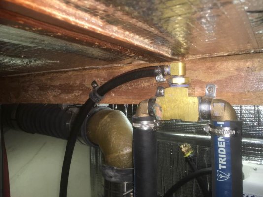
This is a photo of the fitting at the top of the raw water loop between the transmission cooler and the exhaust mixing elbow. The small hose appears to be some sort of "piss line" connected to the lift muffler. I have not been able to identify the type of fitting as I cannot locate it on either the "Western Marine" or "West Marine" websites. I suspect that it might be brass rather than bronze.
IMG_1685.jpg

Jim
 
It's a brass 90 Female on at least one side

Cant tell the thread size, and cant tell if the part coming out the bottom is a male thread or a female thread and a straight nipple.

So... It could either be a 90 which would have two FPT, or a "street 90" which would have one MPT and one FPT

The top is a male thread hose barb.
 
This is a photo of the fitting at the top of the raw water loop between the transmission cooler and the exhaust mixing elbow. The small hose appears to be some sort of "piss line" connected to the lift muffler. I have not been able to identify the type of fitting as I cannot locate it on either the "Western Marine" or "West Marine" websites. I suspect that it might be brass rather than bronze.

View attachment 60253

Jim
Can`t help with ID unfortunately, but keen to know what the small black pipe does (a piss line???):blush:
 
Greetings,
Mr. Bb. I suspect a "piss line" is any hose/pipe that is not meant for a constant flow of liquid but simply to drain an occasional flow like an AC drain. My guess anyway...
 
Go to Grainger. Search extruded female tee in brass fittings. You will find a picture of one there. I wonder if the small line is intended as a siphon break for the loop.
 
If the fitting is supposed to act as a siphon break, the vent isn't supposed to go down. It's supposed to be horizontal out the side of the boat or up. Best to read up on lift mufflers and siphon breaks. Think Tony Athens probably has a good explanation on his site.

Ted
 
Go to Grainger. Search extruded female tee in brass fittings. You will find a picture of one there. I wonder if the small line is intended as a siphon break for the loop.


Thanks! That's what I was looking for. Thanks for the quick response gentlemen!

https://www.grainger.com/product/PARKER-Brass-Extruded-Female-Tee-13Y898

The main lines connect using 2 X 90 degree threaded elbows with hose barbs. Not sure if these are brass or bronze.

The smaller line connects with a reducer and an elbow. I'm not sure about the type of brass here.

Should I be concerned with the use of brass here?

Jim
 
Thanks Tolly. Greenline is a great place and have helped me in the past with propane fittings, etc. For now, I just want to understand what I have and perhaps the length of it's useful life expectancy.
 
You should be able to buy all that stuff at any good hardware store.

It's looks like nothing but a T, a street L and some hose barbs.
 
It is a plain old brass T that is used for a siphon break I would think.


It is fine being brass ass it is not under water or holds any pressure...so when it leaks in 40 years, $10 from Home Depot and you are back at it. The thinner brass nipples will probably go first which I think would be a bigger issue but I would just hit the assembly every year pretty hard and if it stays intact...probably good for another one. Sounds crude but the other solution is go plastic or bronze.

I spent $60 on a Vetus setup...but woulda, coulda been happy with a Home Depot home made one.


Mine really is only a vent, no anti siphon valve in it....just a T. That way salt build up wouldn't possible create a siphon and ruin your engine.
 
Last edited:
If the fitting is supposed to act as a siphon break, the vent isn't supposed to go down. It's supposed to be horizontal out the side of the boat or up. Best to read up on lift mufflers and siphon breaks. Think Tony Athens probably has a good explanation on his site.

Ted


Yes, I am working through some of this. I'm not sure why the OP followed this approach.

Jim
 
Yes, I am working through some of this. I'm not sure why the OP followed this approach.

Jim

Jim: If it's any help, I was on another KK42 which has American Diesel's replacement for the Ford Lehman installed. It was plumbed the same as yours with the top of the loop plumbed into the water lift muffler. Have you called AD or Krogen?
 
Jim: If it's any help, I was on another KK42 which has American Diesel's replacement for the Ford Lehman installed. It was plumbed the same as yours with the top of the loop plumbed into the water lift muffler. Have you called AD or Krogen?


Hmmm! No, I'm just starting to work through this.
 
I have a similar fitting on a Westerbeke genset exhaust system. It exits just above the water line. I was told it served as a "teltale" in that you can hear it from the cockpit pouring exhaust water overboard, letting me know that the impeller is doing its job. The exhaust exit is beneath the swim step and its hard to see cooling water coming out.
 
Where this one is...from the photo...pretty sure it is a siphon break...

Pissing water may or may not happen based on flow and hose sizing.
 
I think siphon breaks need a one way valve to function well (lets air in one way, closes if any water pressure the other way). This is the one on my boat

Edit: PS: This little piece of plastic lasted 27 years before I replaced it:)
 
Last edited:
Is there anything wrong with the one now?


I'm coming around to the likelihood that there is something wrong, that in its current configuration, there may not be an effective siphon break.
 
I'm coming around to the likelihood that there is something wrong, that in its current configuration, there may not be an effective siphon break.

It sounds like your are trying to fix something that may not be broken. :D
 
There is nothing wrong with the setup. When running, some water will run through the hose into the lift muffler. When stopped air will be drawn back into the hose from the muffler and break any syphon.
 
I ordered an anti-siphon from American Diesel for the Lehman 135 in my KK42. Came exactly as pictured, including the elbows. Small line also runs to lift muffler. Can't comment on whether that's the way it should be, but the stainless anti-siphon I replaced was plumbed the same way. Hope whatever you're working on goes well!
 
I'm coming around to the likelihood that there is something wrong, that in its current configuration, there may not be an effective siphon break.

In theory it should work. The main hose and the little one both experience the same pressure at the muffler. Both should flow and the little one should prevent backflow if connected to the TOP of the muffler. The only negative IMHO is that you can't see it working.
 
Where this one is...from the photo...pretty sure it is a siphon break...

Pissing water may or may not happen based on flow and hose sizing.

Yes, definitely a siphon break. Our boat came with them . . . plus a twist. The anti-siphon hose routes to the muffler, but there's an additional fitting with a hose (braided in the photo) that routes to the stuffing box and supposedly cools the cutless bearing.

Mine need attention . . . on more than one occasion, the siphon has not broken and water has backed into the muffler from the stuffing box. This has happened on both engines. Luckily, I was in the ER and able to physically break the siphon before water backed up into the exhaust. In my case, at least, I think this is a flawed design because the siphon can be maintained after the engine shuts down. It probably needs a true physical siphon break at the apex of the anti-siphon tube.


After reading the posts, I figure it is designed to be both - a tell tale "pissing line" to show there is water flow AND an anti siphon BUT it doesnt make sense - a tell tale needs to be visible to show that the system is working - plumbed directly into the exhaust doesn't do that. It would work as an anti syphon but isn't the raw water system open, if the exhausts are above the water line, and therefore it couldn't back syphon?
 
If the fitting is supposed to act as a siphon break, the vent isn't supposed to go down. It's supposed to be horizontal out the side of the boat or up. Best to read up on lift mufflers and siphon breaks. Think Tony Athens probably has a good explanation on his site.
Ted
And...
After reading the posts, I figure it is designed to be both - a tell tale "pissing line" to show there is water flow AND an anti siphon BUT it doesnt make sense - a tell tale needs to be visible to show that the system is working - plumbed directly into the exhaust doesn't do that. It would work as an anti syphon but isn't the raw water system open, if the exhausts are above the water line, and therefore it couldn't back syphon?

On engine shutdown, in theory the head pressure in the vent line should exceed the the head pressure in the downstream line to the mixing elbow, so it siphons into the lift pump. That's the working theory, I believe. The devil is in the details, and certain situations might prevent that from happening.

My intent with this thread is to understand this design, so if modifications are advisable, I can or should do them. Thanks for the debate.

Jim
 

Latest posts

Back
Top Bottom