I have 2.25" stainless shafts with the SAE-standard 1:16 taper. I have been offered new props with the right diameter & pitch and bored for a 2.25" shaft BUT with a taper of 1:12 for some reason. I assume the two tapers must match....can the mis-match be fixed and if so, what is involved in doing this: or do I walk away?
You are using an out of date browser. It may not display this or other websites correctly.
You should upgrade or use an alternative browser.
You should upgrade or use an alternative browser.
Matching Shaft & Prop Tapers
- Thread starter Aquabelle
- Start date
The friendliest place on the web for anyone who enjoys boating.
If you have answers, please help by responding to the unanswered posts.
If you have answers, please help by responding to the unanswered posts.
Alabama Boater
Senior Member
- Joined
- Apr 18, 2016
- Messages
- 110
- Location
- USA
- Vessel Name
- Always Something!
- Vessel Make
- Tiara 3700 open
Tapers must match. The 1:12 can be rebored to 1:16 as the small end is less diameter than what your shafts are. The key way will need to be broached to the 1:16 taper. You would need to find a good machine shop that has the proper equipment and fixtures. Cost in USA to do rebore would be in $250 or more each. Things can go wrong when machining, so for me, must start out at very good price.
Thanks. I called an experienced machine shop and they told me the re-bore'd props would sit further forward on the shaft than my existing. Said it should be "no problem" to put a spacer between prop and prop nut. Any downside in doing this?
Alabama Boater
Senior Member
- Joined
- Apr 18, 2016
- Messages
- 110
- Location
- USA
- Vessel Name
- Always Something!
- Vessel Make
- Tiara 3700 open
You should not need a spacer unless the length of the hub is shorter on the 1:12 props. The front of the hub @ 2.25" diameter would be in the same position as your current prop but if the hub is shorter the rear would be forward by the difference in hub length. If the set up is done correctly, the large end of the 2.25" bore has no material removed. That large diameter is used to center the boring setup. It should be able to center at 0.0005" total run out. I have heard of some shops using a taper reamer but I am not familiar with the set up used.
Thanks again Al Boater...& I realize I mis-typed. The shop said the fwd point on the shaft would obviously remain the same as the hub's opening would remain at 2.25". But re-tapering the bore from 12 to 16 would shorten/narrow the hub (it is 5.75" now). However, I see what you mean...it all depends what my current props' hub thickness is...and since the boat is in the water I have no idea. Aquabelle is about to haul out for antifoul and I'm having the port shaft pulled to get a really good go at cleaning out a problematic traditional stuffing box (packing space larger on one side than the other, so some shaft misalignment I think. I'll replace the cutlass bearing at same time). I'll get the shaft checked for straightness and if as I suspect, there's corrosion at the stuffing box connection point, I'll get the shaft spray-welded/polished in that spot too. Anyway, while all that is going on I'll have the yard check that the shaft really is standard SAE 1:16 and they can measure the current props' hub thickness too. I won't rush to throw out my old manganese-bronze props just yet...but I might not send them off for reconditioning either, if all the measuring suggests the new ones might be a go with a re-bore. Around US$380 per prop here for changing taper to 16 plus costs of getting props to/from the shop. US$975 + transport for reconditioning of both existing props, so I'll keep that in my pocket for now.
Appreciate your input. Will update post & add a photo when hauled out in a couple weeks
Appreciate your input. Will update post & add a photo when hauled out in a couple weeks
An interim update. I went ahead and bought the new Nibral props & they are in the shop having their bore tapers changed from 12 to 16. The shop suggested I also send them one of my existing props so they could get the taper even better matched to the shafts. Aquabelle was slipped Friday morning and the stb prop was taken off and sent to the prop shop as the very 1st job. The prop shop will also make bronze spacers to take up any difference in prop hub length between the re-tapered new and the old props, per posts #4 & 5 above. I left the port prop on to allow us to explore the shaft/stuffing box issues per post #5 with the prop weight bearing....and it soon became obvious that both the stern and the intermediate cutlass bearings are worn & need replacing....lots of slop in both. I am hoping this is the principal cause of the stuffing box problems (apart from the bad packing job done at last haul-out). Port prop was also then removed and we'll pull the shaft on Monday & inspect for corrosion at stuffing/bearing points; and straightness.
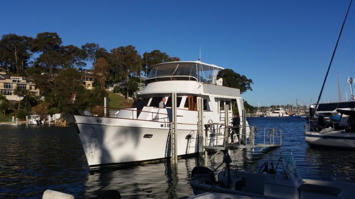
Attached is a pic of vessel up on slip; and another showing the PropSpeed on the props ( also on the shafts, though not in the photo) still un-fouled after 2 1/2 years & untouched by divers. Although the Australian members of TF are all PropSpeed converts, I know some of our US friends are sceptical...but take a look at the rudders (not a great photo I know...sorry, was a bit distracted). I normally get PropSpeed applied not just to props & shafts but to the rudders, skegs and bow thruster metals too. Last time I was hauled, at a different yard to my usual, I let them talk me into saving a few $$ by not applying PropSpeed to rudders & skegs. Instead they took back to bare, epoxied and applied a hard anti-foul (the hull always gets abalative). 4 months before the current haul-out, I had to get a diver to clean the un-PropSpeed'd running gear....and now, just 4 months later, all is severely foul'd with barnacles! The photo doesn't do the degree of foul'ing justice, but it is so extreme the yard is going to charge me a little more for the extra time in dealing with it.
I'll try to take better photos on Monday.
Attachments


Some progress and new learnings: the prop shop called me having examined the original props and compared to new, to say the old props sat well back on the shaft taper and that the new would be much further forward. Was I sure there was enough distance between original props and the aft skeg to accommodate this? I had the slipway guys measure up and reported a 48mm (~2”) gap available; happily the prop shop said this would be OK. The keyways of the original & new props were also different, so now as well as re-tapering to 16 & making up bronze spacers, they’ll also make up new keys. Props will be prop-scanned and balanced/matched also.
Meanwhile back at the slip, the team seemed to have no problems getting the Port shaft out….all 3.9m x 58mm (12.8’ x 2 ¼”) of it. As expected, pretty severe corrosion on the stuffing box end but good everywhere else. Photo below shows 200mm (7 3/4”) corroded section but only 45mm (1 ¾”) of this is within the packing area of the stuffing box; the balance made for an unattractive but harmless view between SB & trannie. This corrosion was obviously the explanation for the Port SB’s steady drip despite re-packing over the last 10 years; and the deterioration in the cutlass bearings since the last haul-out 2 ½ years ago must have exacerbated this by letting the shaft sit out-of-centre through the SB.
The shaft is double-tapered and so would usually have been reversible…but for some reason, the thread on the prop end is 1 ½” but only 1 ¼” at the trannie end. The yard kindly lent me their truck so with the prop shaft & coupling loaded, it was off for the 2-hour drive from Sydney’s eastern edge to an industrial area to the west, to meet up with a spray-welding outfit. When they saw my interest in the process, I was given a full tour of the facility. Pretty amazing, they spray-weld all kinds of coatings, not just the stainless I need: including hi-tech ceramics.
With the shaft removed, the worn cutlass bearings x2 were removed…and we found the ‘spares’ left on board by the previous owner 10 years ago didn’t fit! Also, there is a bearing behind the stuffing box itself in the stern tube and this had almost entirely disappeared. (The SB is bolted direct to the aft engine room bulkhead….no rubber hose….and right behind this is the stern tube with this newly-discovered bearing.) The slipway guys feel this bearing is redundant, as the shaft is supported by two bearings on the hull and by the SB itself…but since we’ve come this far, I told them to go ahead and replace the shaft tube bearing as well, so the SB operates just as a gland. I have to believe this will allow the SB to do as little work as possible.
The slipway team got the new anti-fouling done (but not PropSpeed). Now, while we wait for work on the props and the shaft to catch up, Aquabelle has been un-slipped and is sitting out on a mooring.
Attachments


Last edited:
- Joined
- Mar 17, 2012
- Messages
- 4,276
- Location
- Australia
- Vessel Name
- Insequent
- Vessel Make
- Ocean Alexander 50 Mk I
Good progress! It sounds like the guys involved are all knowledgeable and pragmatic. Are you going to pull the other shaft and check it and the bearings as well? I look forward to you getting it all completed and reporting back on sea trials with the new props!
Brian: Stbd SB has always run cool with zero drips and we try as we might, we couldn't get any wriggle between shaft & skeg bearings on Stb side either....so I don't intend to disturb this. Will re-check Stb bearings at next haul-out in 2 1/2 years: at least now I know what to look for and what's involved/required to address (and who to go for: amazingly I've only been able to find the one spray-welding shop in Sydney and the various marina guys I called around to prior didn't even know of this one !) I did mean to ask about your original (still current?) SB's...are they like mine, bolted direct to aft bulkhead...or did/do they have flexible rubber hose components?
BruceK
Moderator Emeritus
- Joined
- Oct 31, 2011
- Messages
- 13,347
- Vessel Name
- Sojourn
- Vessel Make
- Integrity 386
Aquabelle, what prop & shaft shop you are using? I understood Porters were the go to experts, it sounds like you found someone else.

Aquabelle, what prop & shaft shop you are using? I understood Porters were the go to experts, it sounds like you found someone else.
Hi Bruce: I bought the props from a shop in Brisbane and sent them direct to Porters here in Sydney for the re-tapering & associated work. The shaft was pulled out by Newport Marine Services (NMS: at Royal Motor Yacht Club at Newport on Pittwater) and is with Flame Coatings for spray-welding of the corrosion. The shaft will come straight back from them to NMS...nothing for Porters to do with that, as I also sent an original prop into Porters so they could work off that, not the shaft.
Brian: that is EXACTLY the SB I have too...but where you have a block between stringers, I have the full aft engine room bulkhead. I'm now willing to bet that if you removed your shaft and in-bolted that SB from the block, you would see looking into the 'glass tube visible behind that block, another rubber bearing. Unless there is something behind the block, I'd say the only access to that rubber bearing is by 1st removing the SB, as I am doing on Thursday a.m.. Do you have a photo looking the other way, from behind the block the SB is mounted to....or do you recall if the glass tube just mates up to the back of that block with no fittings, etc?
- Joined
- Mar 17, 2012
- Messages
- 4,276
- Location
- Australia
- Vessel Name
- Insequent
- Vessel Make
- Ocean Alexander 50 Mk I
Paul
The glass tube just mates to the block. There are no fittings of any kind aft of the block in the pic. No idea whether I have the rubber bearing you refer to. During my refit I had new shafts and bearings installed, but it must have been done during one of my visits back to Brisbane. I don't know if the SB was unbolted at the time. I can't recall seeing the SB without a shaft in it either.
The glass tube just mates to the block. There are no fittings of any kind aft of the block in the pic. No idea whether I have the rubber bearing you refer to. During my refit I had new shafts and bearings installed, but it must have been done during one of my visits back to Brisbane. I don't know if the SB was unbolted at the time. I can't recall seeing the SB without a shaft in it either.
Last edited:
Brian: you can't see the bearing in that tube unless the shaft is out AND the compression plate & the packing are removed. The bearing seems to fit inside a bronze tube; I am not sure whether this is bolted to or is even an integral part of the SB itself. I'll know more when my SB is actually unbolted & removed. I'm hoping an experienced TF member has come across this setup before & will comment. I don't think this belt-&-braces approach is used on contemporary recreational vessels; it may have been an Ed Monk Snr special.
- Joined
- Mar 17, 2012
- Messages
- 4,276
- Location
- Australia
- Vessel Name
- Insequent
- Vessel Make
- Ocean Alexander 50 Mk I
Paul
I will be interested to see what you discover. I'm sure the OA yard built our boats almost identical. Other than yours being one of the handful of flushdeck configurations.
By the way, I believe it was Ed Monk Jnr that was responsible for the Mark I design. Of course he may may well have taken inspiration from his father, or Art DeFever, or others who produced the 'classic' raised pilothouse design as well.
What I don't know is how much Ed was involved in the detail, such as the SB we are talking about. There may well have been others responsible for this area, or a 'standard' Taiwanese approach to things like this. But I do believe there was a commitment to quality and good design. They were built at a time when knowledge was rapidly evolving, and yes, when Fleming came along a few years later they were built a little better. Indeed part of the demise of the Mark I was that they were expensive to build. Hence the Mark II. Cheaper to build, a nice boat for sure but I don't think it has ever had the enduring appeal of the Mark I. Hats off to both Ed Monk and Ocean Alexander for both!
Quite right Brian...it was Ed Monk, Jr. Here's a link to a recently re-launched OA site. You will see my motor yacht model pictured....3rd photo down on left side. Heritage - Ocean Alexander The 3rd partner, with Ed Monk & Alex Chueh, was an Australian...a Gold Coast-based yacht broker, so we have a connection of sorts there too! I have an electrical wiring diagram original to my boat, hand-lettered and signed by Alex Chueh.
Paul g
Paul g
Last edited:
Brian: I THINK I now know what to expect when the SB is unbolted and removed. I reckon it will be like the big heavy Model 102LB shown on the attachment to this post. It incorporates a "1/3-length standard rubber sleeve bearing" right behind the packing rings. The attachment shows a modern Duramax model, but in the early-to-mid '80's companies like Buck Algonquin and Wilcox Crittenden were making this sort of SB too. Of course ours may have been cast in Taiwan....I have found a few bronze fittings that have Chinese characters on their in-finished undersides so the yard must have made these or had them made locally...perhaps the SB's were the same. I imagine they would have been high-cost items to bring in from the States.
Attachments
- Joined
- Mar 17, 2012
- Messages
- 4,276
- Location
- Australia
- Vessel Name
- Insequent
- Vessel Make
- Ocean Alexander 50 Mk I
Paul
I don't think I had any rubber, based on my refit invoices. All I could find was 6 x bearings. They were 2" x 2 5/8" x 8" in size.
Your set-up is a little different in that shaft size is larger. But was that original, or a mod when your PO installed the larger engines?
I don't think I had any rubber, based on my refit invoices. All I could find was 6 x bearings. They were 2" x 2 5/8" x 8" in size.
Your set-up is a little different in that shaft size is larger. But was that original, or a mod when your PO installed the larger engines?
Brian: 6 bearings is 3 per side. One for the big skeg against the prop; one for the intermediate bearing; and the 3rd.....for the stuffing box?? Maritime archaeology begins tomorrow...
I don't know if the shaft was replaced with the engines. I do know the skeg and intermediate bearing holders have plenty of room to take different thickness cutlass bearings. The new ones (naval brass shells) for the two skegs have to be shimmed down a little to fit, but these things come in different outer wall thicknesses (while remaining constant for shaft of) for just that purpose apparently.
I don't know if the shaft was replaced with the engines. I do know the skeg and intermediate bearing holders have plenty of room to take different thickness cutlass bearings. The new ones (naval brass shells) for the two skegs have to be shimmed down a little to fit, but these things come in different outer wall thicknesses (while remaining constant for shaft of) for just that purpose apparently.
- Joined
- Mar 17, 2012
- Messages
- 4,276
- Location
- Australia
- Vessel Name
- Insequent
- Vessel Make
- Ocean Alexander 50 Mk I
Brian: 6 bearings is 3 per side. One for the big skeg against the prop; one for the intermediate bearing; and the 3rd.....for the stuffing box?? Maritime archaeology begins tomorrow...
I don't know if the shaft was replaced with the engines. I do know the skeg and intermediate bearing holders have plenty of room to take different thickness cutlass bearings. The new ones (naval brass shells) for the two skegs have to be shimmed down a little to fit, but these things come in different outer wall thicknesses (while remaining constant for shaft of) for just that purpose apparently.
Yes, I believe my stuffing box has the same bearing as the skeg and intermediate strut. And so I doubt there would be rubber in there as well, but I really don't know.
Two Steps Fwd, One Aft: I'll cover off progress in a few separate posts. First, the shaft...
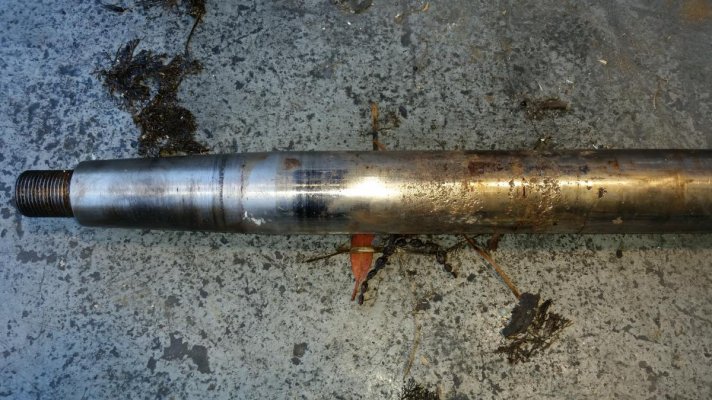
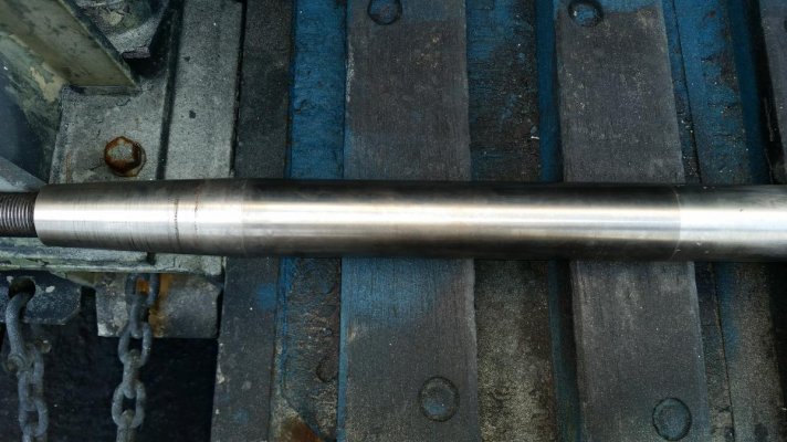
Per earlier posts, the shaft was found to be pitted/corroded over the section within & fwd of the stuffing box. I found a now-rare (at least in Sydney) spray welding outfit and took the 3.9m shaft to them and retrieved it 48 hours later. I am really impressed with the work they did, the care shown and the moderate price charged...and the yard engineer was impressed too. I'm happy to recommend Flame Coatings of Ingleburn: Thermal Spraying, Spray Coating, Welding, Arc Spraying | Flame Coatings, Sydney
A pre-treatment photo appears below, along with wide and detail views of the repaired shaft....which is now back at the slipway and ready to be re-installed when SB is ready to accept it.
Attachments


- Joined
- Mar 17, 2012
- Messages
- 4,276
- Location
- Australia
- Vessel Name
- Insequent
- Vessel Make
- Ocean Alexander 50 Mk I
Paul:
Glad the thermal spraying went well. They look to be well set-up and have a lot of expertise. I had some potential crevice corrosion at the SB, which was why I replaced the shafts. Maybe I could have repaired the shafts instead!!
But, as the thread below discusses, shaft failures are very likely more often caused by poor taper fit and particularly keyways. I found the thread very informative.
http://www.trawlerforum.com/forums/s6/shaft-broke-off-cutlass-bearing-28863-2.html
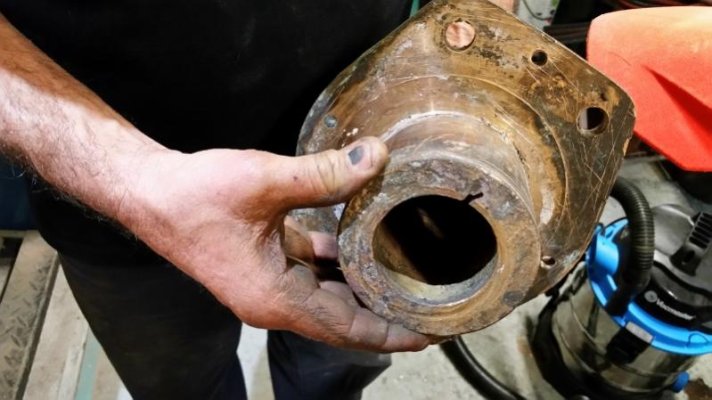
Now, the mysterious stuffing box….or not so mysterious, as it turned out to be as I’d guessed in post #18 above. No shipwright or engineer at the yard had ever seen one like this and the DuraMax pdf I attached at post #18 was all they had to go by. An experienced shipwright took it partially apart and discovered two “puller/pusher” tapped holes. Thin flat stainless plates were inserted between the bronze backing plate and the hull (not easy) and threaded rods were then screwed in, which with a bit of ‘encouragement’ via a pipe and a mallet from outside back up the shaft tube, finally pushed the whole contraption free of the bulkhead & into the engine room.
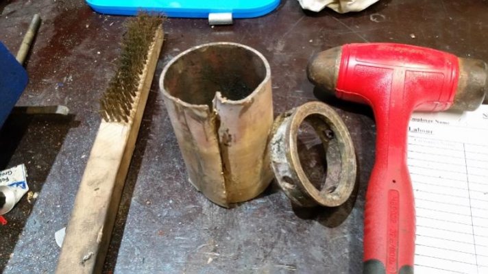
The 1st photo below shows the SB out of the boat, fwd side, with one of the long push-bolts in place. The 2nd photo looks down through the SB while it was still in situ; if you zoom the photo, you may be able to make out the almost-worn-to-nothing rubber bearing fluting.
The 3rd photo shows the aft side of the SB, the tube behind the bulkhead, which contains a rubber bearing….already removed in this photo, to show the tube has a ‘lip’ to retain the bearing, which has to be inserted before the packing from the engine-room side.
The 4th photo shows the removed bearing and a retaining ring that sits between the packing and the bearing….this detail for the benefit of any OA owners and others with this unusual SB that may be faced with removal down the track. It seems that today, these SB’s are made only for shafts of 4” and greater. I’d guess that many are out there and have been re-packed regularly, with their owners oblivious to the rubber bearing that sits behind the packing space and which, while long-lived if the running gear remains undamaged, does eventually wear out and deserves replacement.
The SB will be completely cleaned up and a new bearing inserted tomorrow. I probably won’t be around to take a pic of the finished object unfortunately, but I’ll try to get the yard to do so.
Attachments


Last edited:
OK, with shaft and SB sorted...almost....we struck an unexpected issue with the new props. As noted in earlier posts, the new props sit higher up the taper than the originals so the prop shop made up ~15mm thick bronze spacers, to go between the prop hubs and the locking nut. Photo 1 below shows one of the new props and these spacers.
But when the yard manager went to mount the Stb prop, he realized that the spacers wouldn't work with the original prop nut. The 2nd photo shows one of the old props with the prop nut sitting on top of it. This is a large domed nut and is the only nut used on the shaft: no smaller locking nut, no split pin to retain the nut. Instead, you can see a hole drilled through the dome nut flange, a set/grub screw goes through this hole & seats in a tapped hole in the original prop. We hadn't sent this somewhat unusual domed nut to the prop shop with the old prop and the yard manager and I hadn't been around to see this set-up when the original props were removed. Of course there is no hole thru the spacers and no tapped hole in the new props.
After a hurried phone consult with the prop shop, we have decided to drill a hole through the SIDE of the domed nut; fully torque it up against the new prop; and then drill a dimple into the shaft's threaded section. We'll then use a set/grub screw through the domed nut onto the shaft.
All this plus the work to finish up and re-install the SB will take another yard day....and I cannot hang around due to another commitment, so I'll have to leave it to the guys (they will likely be glad to see the back of me after all my hovering and photo-snapping!). I'll report back after I get back to the boat in a few days and make the 4 hour trip from the yard on Pittwater back to Aquabelle's home marina on Sydney Harbour.
Attachments


Ski in NC
Technical Guru
Can you ditch the domed nut and go with either castellated nut or double nuts with cotter key?
Is the shaft standard SAE dimensions?
May still need a bushing but that is easy to make with a lathe from an old nut, etc.
Not liking the domed nut with a little lock screw.
Is the shaft standard SAE dimensions?
May still need a bushing but that is easy to make with a lathe from an old nut, etc.
Not liking the domed nut with a little lock screw.
Eric...great to have your experienced eye on this. Yes, the shafts are standard SAE with 1:16 taper/ 2 1/4" od. We did talk about reverting to standard prop nuts (castellated or otherwise) but we'd then have to drill right through the shafts for the cotter pins. Only one shaft was pulled so that would involve pulling the second shaft (which has no issues) and the engineers at the yard said they'd have to send them off to a specialist shop as the shafts are too hard for their gear....so a lot of time/delay/cost.
I was surprised to learn the big dome nuts were fastened directly into the aft face of the original props (have you seen this done before?)...but it clearly worked for some 3500 hours of operation. I'm not sure doing much the same thing, but sideways and into a dimple on the shaft, is any less secure? The domed nuts are really substantial...the set-screw needn't be small.
I am not familiar with all the options for prop nuts; is there a set-up I could use that doesn't require drilling thru the shafts to take cotter pins?
Is this an acceptable alternative to locking the prop nut on a larger shaft with 26 1/2" prop? Called a TAB WASHER & explained here: http://www.hamblepropellers.com/80735/info.php?p=9