Keel cooler size and specs?

The friendliest place on the web for anyone who enjoys boating.
If you have answers, please help by responding to the unanswered posts.

Transaxial

Senior Member
Joined
Jul 20, 2016
Messages
101
Location
Canada
Vessel Name
Soul Fisher
Vessel Make
Palmer
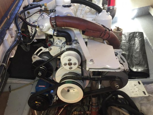
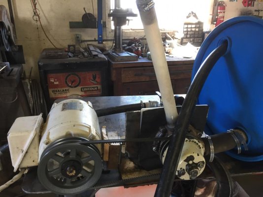
I am trying to improve a chronic overheating problem for my old Mitsubishi 6D14. It is 6.5 liters or 400 Cid and na. I bought the boat a year ago and all I really know for sure is the PO had some overheating problems too. It could be rated as continuous power output which would be 115 hp @ 2800 rpm or more likely 126 hp at 2800. That would generate a water jacket heat rejection of 234,000 btu according to the service manual, which I think is 100,000 low, and require a coolant flow of 58 gpm, or more if the 234,000 is low. I have rebuilt the old aluminum water pump which involved aluminum welding the erosion that caused 1/4" gaps between the impeller vanes and the housing, and now machining the gap to be only .020. I set up the pump to test flow and pressure on the welding table and at 2500 rpm and 8 psi it is flowing 70 + gpm. That seems good and is up to specs and would be achieved at 2300 engine rpm. That is what I know. What I don't know starts here. This is a 40 year old engine and no one can even match S/N to get the right water pump so we guessed and it seems like the new pump is way low on output. A flow meter is showing only 10 gpm at 1800 pump rpm. Too low. So we need to try the old rebuilt pump first. Problem is the boat is coming out of the water for annual antifoul, zincs and new transducers for new Simrad system, new hydraulic bow thruster. So my main question is, what does my engine need for a keel cooler? It has run for 40 years with an undersized cooling system the way I see it and I am adding a hydraulic cooler. The local boatyard and mechanics put in a request for sizing to Walter and the 234,000 number right out of the book is what got submitted for a heat rejection figure. But this boat has a dry stack and an exhaust cooler box over the standard truck exhaust manifold and a transmission cooler and a hydraulic cooler. All cooled by the engine antifreeze loop. This is way too much resistance in the flow. If the pressure is increased with an additional pump, to achieve the 60 or 70 gpm required, the velocity spikes up over 12 fpm and off the chart. The desired flow rate is 2 to 8 ft per min. It all points to the fact that I need a dedicated cooler for the engine with about 2" ports and able to handle 250 to 300,000 btu??? The remaining 3 coolers would be handled by the existing 40 ?? Ft of 1 1/4" copper keel cooler and circulated by a Grundfoss 26 99 electric circ pump. It seems to be the only way to get enough total heat out of this boat and keep all the volume and velocity figures in a good range. I have been digging up some of my old diesel engineering text books and a good formula for starters to determine flow in us gpm is total btu divided by 500 x delta T. I realize that delta T depends on water temp you are cruising in and a lot of other factors like flow rate, cooler size, etc. and the factor of 500 is only 450 for antifreeze. Too many variables here without some experience weighing in. If I had just let the marina do its thing, I would have had a cooler sized for just the water jacket heat rejection. The extra coolers that will be adding 200,000 btu were never mentioned in the quote. Can anyone give me some real world experience on this?

Another approach to the total btu produced is to use 7 gallons per hour fuel burned at wot which almost never happens, x 138,000 btu per gallon of diesel which equals 980,000 btu approx. About 33% goes to each of engine coolant, exhaust, and rotary energy. Radiant heat off block also accounts for 7%. Where else would all this heat go? Which approach is correct for sizing this keel cooler?
 
I can't believe that the boat has been overheating for 40 years. I also know that the Mitsubishi engine is a bit of an orphan out here. Where is Tofield?

I know nothing about thermodynamics but the hydraulic cooler can be an issue. Hydraulics can produce a LOT of heat. What sort of pump does it have? The way to tell if its near the end of its life is to measure the flow from the case drain according to the specs from the manufacturer. Hydraulic pump failing might be the source of the excess heat. If it is not a PTO pump but driven by a belt, try disconnecting the hydraulics and see how the heating goes?

I have a keel-cooled engine but the oil cooler is inside the engine jacket and the transmission is also cooled by antifreeze.

You might also change the coolant. When I bought my boat there was no record of it having been changed and even with the correct additive package its probably good for 5 years tops. Old fluid/depleted additives can cause a healthy diesel to overheat. I had close to 200 litres to toss when I changed mine. It comes out of the keel cooler like a cow peeing on a flat rock! After changing the fluid I have to bleed and bleed the system to get all the air out and I had to throw out the Cummins overflow tank and replace it with a much larger tank as expansion was an issue at WOT. Is your overflow tank properly sized? I thought I was overheating too as the overflow tank filled right up and overflowed.

That's all I can think of, with your repaired pump there should be enough flow to keep it cooled if the total flow is through the block. Does your system circulate the entire coolant through the engine without a separate pump and a heat exchanger? Water temperatures are pretty cool here. Also the thermostat must be good, if it does not open properly the engine can overheat from that too.

Oh, check that the cooler is not fouled if it is on the outside of the hull, make sure also that it doesn't cavitate when you are running fast? I have no idea how you would do that.

That's all I can think of...
 
Last edited:
Is that a Farrell hull? She looks nice.
 
For your hydraulics, why not put a seperate cooling circuit in? Water intake through-hull, one exit near the waterline, and run by a hydraulic pump. Pretty simple, and avoids having to stress or overload the engine cooling circuit. It could be sized to handle the transmission cooling needs as well, and then your existing engine cooling may well be fine.

For your engine cooling, systematically work through all components to verify all is as designed. I, too, doubt it has been overheating all its life.
 
The problem might be with the engine it self.

Truck engines are expected to be at full power only for short periods of time , "up that hill" , so 15 -30 min takes care of most full throttle work.

IF the internal engine build , water passages and water pump volume are not able to handle the full cooling load , the trucker is forced to back off.


ALL of the mfg of keel coolers will speck systems for worst case , 95F water and full tilt on the engine, if your keel cooler was properly selected , it could just be the engine limits.

"You might also change the coolant." You might also clean the engine with 2 part cleanser

Yes coolant with antifreex is less efficient (5/8) at heat transfer than plain water.

A test ride with just plain water might be an eye opener.

Just water with water pump lube and anti corrosion protection might solve the problem , after the coolant circuits are clean.
 
Last edited:
To troubleshoot KC heating issues, you need to do a temp study underway and look at the temp of coolant entering cooler and temp returning from cooler. If cooler is undersized, return temp will be high. If flow is low, return temp will be low yet engine temp high.

And what is your criterion for overheating? How hot does engine get and where are you measuring that? Some engines run at higher temps normally.

May also be able to have a custom made pulley for the engine circ pump to raise its rpm relative to crank rpm.
 
Thanks for the replies guys! Your ideas and questions are right on the money. I have to apologize for not including more detail in my original post but it was getting really long as it was. To answer some of your questions like where is Tofield? I am quite new to this forum, to boating, to west coast life aND when I signed on to TF I just put in my lifelong home town, 40 miles east of Edmonton Ab but the boat lives in Nanaimo BC. With regard to the questions about the engine and cooling system, I have been working on all the more obvious solutions like testing and changing thermostats, flushing and changing antifreeze but not doing a two part cleaner, checking hoses and cleaning up plumbing, installing a new water pump that I think is a very big part of the current overheating problem that the boat can not even cruise slow, flow tests on water pump on and off the boat, custom built new smaller water pump pullys to increase pump speed 20%, consulting with several local techs and marinas to see if someone can pinpoint the problems and what to do to make it right. In short, all my calculations from learning thermodynamics of btu, flow, speed of flow, pressure, resistance, heat transfer, etc have led me to the conclusion that the keel cooler on my boat may have been sized for engine water jacket heat rejection only and not the additional 160 to 200,000 btu from the dry stack exhaust cooler and BW72 transmission cooler. The engine kind of gets by at a 6 kt cruise where the power required is only 30 to 40 hp but at any higher power requirement the heat is just not getting away. So what I am thinking of doing is to add a new Walter keel cooler that can handle the main engine heat load with a 2" flow and low back pressure and velocity just using the engine water pump. The extra 3 coolers will be handled by the old keel cooler loop and circulation by the little Grundfoss 25 99 electric pump. I think this addition would be close to doubling the current btu capacity of the system. Has anyone used an Amot model B thermostatic control valve for full flow temp regulation of the engine to reduce flow loss through a conventional thermostat? Thanks again for all your ideas.
 
Is that a Farrell hull? She looks nice.

Thanks! It seems to be a pretty solid old hull that was completely rebuilt about 1998. I believe it is a Palmer but I met up with Barry Farrell at the dock one day, had a very interesting visit with him, and he even thought it looked like one of the 300 or so boats he designed and built. As with most old boats it needs a little tlc and I do want to get it up to a reliable status, specially in the mechanical dept. This lack of cooling problem has given me the runaround for too long so I want to do a redesign of some things.
 
To troubleshoot KC heating issues, you need to do a temp study underway and look at the temp of coolant entering cooler and temp returning from cooler. If cooler is undersized, return temp will be high. If flow is low, return temp will be low yet engine temp high.

And what is your criterion for overheating? How hot does engine get and where are you measuring that? Some engines run at higher temps normally.

May also be able to have a custom made pulley for the engine circ pump to raise its rpm relative to crank rpm.

Very good point about analyzing keel cooler out and return temps. My problem is the engine is getting hot to the boiling point before I can even do any testing. At 1500 rpm not in gear and tied to the dock it runs normal temp but any more load and it starts to climb. At a 1500 rpm sea trial we didn't get half a mile and the temp gauge pegged right over to 250. We were confirming this with an ir gun and do not want a repeat of that. Fortunatly the engine and head seems ok. We really have to try the old rebuilt water pump to see if I can get the temp under control for more testing. I did have a pump pulley built that raises rpm by 20%.There is more than one issue going on here and the new water pump being a dud may be another piece of the puzzle. Your statement that if flow is low, then return temp will be low yet engine temp high seems to be what is happening. This is likely a combination of too low a flow due to a poor water pump, too long a loop of all the coolers in series, and the existing keel cooler loop being too small and short for the load.

Thank you for your advice.
 
Have you done a compression check to ensure its not a head gasket issue?
 
Have you done a compression check to ensure its not a head gasket issue?

Not an actual compression check but we have looked for bubbles in the coolant when under some load and not seen any. Also tied a plastic bag around the filler cap on the reservoir and did not see it puff up. No coolant in oil or oil in coolant. I was concerned about that but think it is good.
 
"200,000 btu from the dry stack exhaust cooler" ????????

I have seen keel coolers that cool exhaust manifolds but never the stack it self.

Why bother ? It would at least double the heat load in the system.

With the early onset of the heat problem 1500 and no load I would look at the injector timing .
 
Last edited:
"200,000 btu from the dry stack exhaust cooler" ????????

I have seen keel coolers that cool exhaust manifolds but never the stack it self.

Why bother ? It would at least double the heat load in the system.

With the early onset of the heat problem 1500 and no load I would look at the injector timing .

I might not have been clear enough. The boat has a dry stack therefore it uses engine coolant in a box around the exhaust manifold to capture that extreme heat right out of the head. The rest of the dry stack is wrapped with insulation . One of the unknowns here is how many btu could be transferred to the cooling system in this manifold cooler?

We are putting the injectors back in today. Will look at timing but the engine has been starting instantly and runs nice.

Thanks FF
 
If coolant from the KC leading back to the engine is cool, then the issue is low flow. If KC was undersized, coolant would exit hot.

Sounds like an issue with the circ pump, which you have already focused on.

Is there a bypass flow path where coolant circs around engine before tstat opens? Most engines have this and some rely on tstat to block this path at high temp. So a tstat wrong for the app can cause too much flow to remain in the bypass loop. How this bypass is handled depends on engine design.

I can see that you know what you are talking about Ski!! We have wondered about too much coolant recirculating through the bypass but you bring it into focus again. If we take out the little 1" 80 degree bypass hose and install a long loop that we can have a ball valve on to be able to 100% shut off that bypass flow, it should tell us if that is a problem. Have you ever seen an AMOT model B thermostic control valve used. I have little luck getting proper parts for this engine so by eliminating the stock thermostat and replacing it with this industrial full flow replacement seems like a win win. It is a full flow T setup that can be ordered in 2" and whatever fully open or closed temp you want. Totally eliminate the stock bypass loop if that is a problem and reduce resistance in the loop to get better flow with the existing stock water pump. We may look at adding a new keel cooler dedicated to just engine cooling at the same time if needed.

Thanks for your on point feedback!

I added a picture of the new water pump installed on the engine showing the bypass loop. It is 1/4" bigger diameter than the old pump. Second picture is the old pump after rebuilding on the test bench I built. It is great to get flow specs, 70 gpm at 8 psi at 2500 rpm and deadheaded it makes 13 psi, exactly what shop manual calls for!!
 

Attachments

  • IMG_0263.jpg
    IMG_0263.jpg
    141.8 KB · Views: 75
  • IMG_0545.jpg
    IMG_0545.jpg
    114.8 KB · Views: 63
Let me expand on Ski's suggestion of doing a heat study around your engine. You need to accurately measure the coolant flow rate and the temps in and out of the KC.

Getting the temps should be easy. Start the engine, put some heavy lines on it and run it at 1,500 rpm in gear and watch the coolant temp rise. If it stabilizes, then shoot the in and out temps with an IR gun. If not then shoot what you get just before overheating. The latter won't tell you exactly how much heat is being rejected to the coolant but it may give you an idea.

Measuring coolant flow rate will be more difficult. I realize that you measured something on the bench, but that doesn't mean a lot installed. I would rig up a way to make up coolant with a big fresh water hose, then disconnect the return line to the KC and temporarily put it in a 5 gallon bucket. Start the motor and rev it in neutral to 1,500 and time how long it takes to fill. It won't take long, ten seconds for 30 gpm.

And 30 gpm at a 20 degree temperature rise equals about 270,000 btu/hr. If you can get to those numbers then you should be able to do at least 50% more at 2,800 (the pump curve won't be linear) or about 400,000 btu/hr which should be enough.

If you can't do 30 gpm at 1,500 engine rpm then you either need a bigger pump, a better pump- ie fixed with a different pulley or rebuilt or as you suggest split the loads between two KC systems. But you need to know what you have before you can develop a solution.

David
 
Can you show us some more photos of the installation?
 
Passed along to me by a reputable marine engineer....

" ...not the additional 160 to 200,000 btu from the dry stack exhaust cooler ..."

OK......The guy needs to look up the definition of a BTU and consider how many pounds of water is in his cooling loop.

Another issue ... cooling the stack is not a great idea. Every pound of fuel burned produces around a pound of water and when the exhaust encounters a cool stack water vapor condenses, collects soot, and sulfur and begins to corrode the exhaust system as well as raining soot and black water droplets all over the boat. Keep the stack hot. "
 
Let me expand on Ski's suggestion of doing a heat study around your engine. You need to accurately measure the coolant flow rate and the temps in and out of the KC.

Getting the temps should be easy. Start the engine, put some heavy lines on it and run it at 1,500 rpm in gear and watch the coolant temp rise. If it stabilizes, then shoot the in and out temps with an IR gun. If not then shoot what you get just before overheating. The latter won't tell you exactly how much heat is being rejected to the coolant but it may give you an idea.

Measuring coolant flow rate will be more difficult. I realize that you measured something on the bench, but that doesn't mean a lot installed. I would rig up a way to make up coolant with a big fresh water hose, then disconnect the return line to the KC and temporarily put it in a 5 gallon bucket. Start the motor and rev it in neutral to 1,500 and time how long it takes to fill. It won't take long, ten seconds for 30 gpm.

And 30 gpm at a 20 degree temperature rise equals about 270,000 btu/hr. If you can get to those numbers then you should be able to do at least 50% more at 2,800 (the pump curve won't be linear) or about 400,000 btu/hr which should be enough.

If you can't do 30 gpm at 1,500 engine rpm then you either need a bigger pump, a better pump- ie fixed with a different pulley or rebuilt or as you suggest split the loads between two KC systems. But you need to know what you have before you can develop a solution.

David
Thanks for your right on the money response. I do have a lot of other data obtained from a few weeks of testing and trying different things. The main problem I think is that my cooling loop is too small a diameter at 1 1/4". It is also very long and complex as it comes out of the tstat at 2" , the big red hose goes around to the rear of the engine into a 1 1/4" transmission cooler, then into the 1 1/2" exhaust cooler box, then into the 40' long 1 1/4" keel cooler pipeing. I have done lots of engineering level calculations that show that to move the 70 gpm I need to remove 500,000 btu total heat load with a delta T of 15 or 20 F , I would need 30 to 40 psi from the pump and then the ft per minute of flow goes off the chart at 15 ft per sec. It always boils down to the existing cooling system being too small. The question is how big does it need to be. Engineers like to have nice exact numbers to plug into their complex formulas which is what I do not have so am looking for some comparative cooling solutions. I think my current engine water pump is not making enough pressure and we changed it yesterday so will get some new temp readings today which I will report. This pump is the one on the test bench so has some known data. Thanks everyone!
 
Can you show us some more photos of the installation?

Here are a couple pics of the 2" hot discharge from the tstat going around to the back of the engine to the transmission cooler in a full series loop, and the into the exhaust manifold cooler box before exiting the er to the 1 1/4" keel cooler under the hull. Too much backpressure to meet the engines maximum friction head after engine outlet of 3 psi.
 

Attachments

  • IMG_0063.jpg
    IMG_0063.jpg
    148.2 KB · Views: 42
  • IMG_0068.jpg
    IMG_0068.jpg
    159.2 KB · Views: 44
  • IMG_0065.jpg
    IMG_0065.jpg
    136.7 KB · Views: 45
If I am seeing this correctly, I would run the hot water from the engine (it will only do that once the thermostat is opened) directly to the keel cooler. I would find a place to tap the jacket (same as you would for a heater connection) and run that through the transmission and hydraulic cooler. The water returning from the KC I would run directly to the engine. That is the way mine is plumbed. Your transmission has a plate on it that will tell you how hot the oil can get, that is a higher limit than what the engine can take.

If you have a loop to a water heater, remember it will also heat up the coolant if it is electrically heated. I would disconnect that loop (connect it in a loop outside the tank) for the time being.

I don't see an overflow bottle. You need a big one (at least a gallon, preferably 2) and it should be mounted above that header tank so that the system will be self-bleeding. I have a Murphy switch on mine in case I spring a leak and start losing coolant. That will be hard to do with your limited space - it might need to go in a cupboard or similar.

I think that without a heat exchanger for the engine and running the others off a loop, not the KC, you will have sufficient cooling if the engine is healthy.

By the way, that red hose looks like its time to change it too.

Good luck!
 
Here are a couple pics of the 2" hot discharge from the tstat going around to the back of the engine to the transmission cooler in a full series loop, and the into the exhaust manifold cooler box before exiting the er to the 1 1/4" keel cooler under the hull. Too much backpressure to meet the engines maximum friction head after engine outlet of 3 psi.

Most transmission coolers are too restrictive to be in the main 2" circuit. The pump bypass malfunction was a very good idea did you ever valve or block it for a test?
I changed over my engine, same aprox HP, from sea water to freshwater cooling many years ago on my lobsterboat. I increased the area of the heat exchanger by 25% as a precaution and has always seemed to be plenty. However I created a parallel flow path b/c the manifold did not have 2" ports nor could they be installed.
In New England many people run dry stacks but I have yet to see a watercooled one. Cooling the manifold is one thing but depending on how much and how cool the piping is it seems to me you could more than double your cooling load.
As an aside: My friend and I just built a harbor launch and used a 45HP antique gas engine with WC manifold. We used the cooler pipes that came with the engine 17' 3/4" pipe. And the propeller so basicly same load. It overheated right away at full load. We increased the length to 30' and problem solved. Maybe the engine was never run at full power b/4. 3/4" pipe is 1" OD so 30' gives maybe 8 sq feet area about 5.5 HP per sq foot.
If I read correctly, you have 13 sq' of area or nearly 10 hp per sq. foot.
 
Last edited:
I think there is some terminology confusion going on here.

The cooled dry exhaust that you describe is more commonly called a wet exhaust manifold and is very common on marine engines. In fact, they are almost universal.

The heat rejection spec for your engine should include everything in the engine coolant loop as supplied by the mfg. This would typically include the main engine water jacket, but also include the wet exhaust manifold. Now I say "should", but its always possible that the spec you have is for the non-marinized engine which would normally not have a wet exhaust manifold. Perhaps there are other clues in the engine specs about whether they are talking about the marine version of the engine? For example, if they talk about the sea water pump, then the spec is surely for the full marine engine and would include coolant heat rejection from the wet manifold.

In contrast, the gear cooler would typically NOT be part of the engine heat rejection spec. However I expect it is minuscule compare to the engine, so not a concern from a heat rejection stand point.

As a reference point, a modern Deere 160HP engine rejects about 350kBTU to the coolant circuit. So something in the 250KBTU range for your engine seems reasonable.

Another point of miscommunication I think has to do with the bypass circuit. Cooling systems have an internal bypass path to allow coolant to continue to circulate while the engine is warming up. You shouldn't screw around with that in any way, and as has been pointed out, using the wrong type of thermostat can defeat the bypass causing all sorts of problems.

Separate from the bypass is the aux heating loop commonly used for heating domestic water and heating the cabin. It has nothing to do with the bypass circuit. The aux heating loop is the thing that is optional and can b valved off or plugged if desired. Manufacturers will also commonly like flow through the aux loop using fittings with fixed opening sizes, and limiting the size of allowed hose, all to prevent over cooling of the engine. I cant tell which of these you have modified, but neither may be a good idea.

BTU specs are one thing, and as you have surmised, unimpeded coolant flow is another thing entirely, and yours indeed seems suspect. A 2" engine hose size, going to 1.5" for the manifold is not great, but I see nothing you can do about that. The subsequent drop to 1.25" for the gear cooler, hose runs, and keel cooler seem very problematic.

But before making any changes, I totally agree with DMarchand and Ski about diagnosing the problem before you plan the remedy. Unless you are getting hot coolant out of the keel cooler, you should assume the cooler is fine.

Another good test would be to measure the coolant pressure somewhere between the pump outlet and the entrance to the gear cooler. You mentioned calculations in the 25 to 35 psi range which is nutty. Specs I've seen call for no more than something like 5 psi back pressure through the external loop. I think your suspicion is correct that you just aren't getting sufficient flow. But temp measurement along the path will confirm one way or another.

I suspect that if you bypassed the gear cooler and ran 1-1/2" or even 2" hose to the cooler that it would work fine, even with the step down to 1-1/4" through the cooler itself.
 
Some more info passed to me....


"Unless you are getting hot coolant out of the keel cooler, you should assume the cooler is fine."

If the flow through the cooler is restricted you can put boiling water in one end and get ice water out the other. This is a heat transfer exercise, there is a difference between heat and temperature. If you pass a small quantity of high temperature coolant through the heat exchanger over a long period the number of BTUs required to be removed to drop the temperature may be quite small. In that case the temperature difference between inlet and outlet is essentially meaningless.

If the coolant flow through the engine is at the design rate and the temperature drop across the heat exchanger is low then it may be assumed the heat transfer area of the cooler is inadequate or is fouled externally.

"I think your suspicion is correct that you just aren't getting sufficient flow. But temp measurement along the path will confirm one way or another."

Temperature measurement alone will not confirm anything other than the temperature at the point of measurement. If the OP correctly determined the rate of coolant flow it is less than 20 percent of design rating so it should be no surprise if the limited number of BTUs entering the keel cooler will be removed and produce a misleading low temperature output while the engine overheats. If flow rate is correct then the temperature differential across the heater is a valid measure of heat exchanger capacity or efficiency. Neither flow nor temperature differential alone should be used as a measure of system efficiency.

His original post stated categorically that the manufacturer's required flow is 58 GPM but actual flow was measured at only 10GPM and stated the engine overheats rapidly when a load is applied. Why all the discussion? It is like someone saying that their light bulb suddenly went dim and when they checked the voltage it was very low but wants to know if something is wrong with the bulb.
 

Latest posts

Back
Top Bottom