Tom.B
Moderator Emeritus
- Joined
- Jul 30, 2009
- Messages
- 5,839
- Location
- USA
- Vessel Name
- Skinny Dippin'
- Vessel Make
- Navigator 4200 Classic
Fuel Wars: Episode II A New Hope
Well, well, well... Thanks to the engineering styling's of a regular member here (I'll let him come out of the closet if he wants to), I have been re-inspired to take the project in a new direction. So, with that, I guess a new thread would be in order to give new eyes to the goings-on.
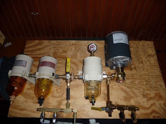
Picture 1 below was sent to me via email.
I studied it long and hard. I almost dismissed it, but gave it a second look today and decided to COMBINE the two ideas. My biggest problem was ego. I was proud of what I had done (with all your help) and didn't want to throw out all the work I had done. All the hours spent at the Grainger website would have seemed wasted. I also feel like Spring is coming and I don't want to still have the system in bits when it happens. BUT... when I dragged it all into the bilge today, I realized it could be better. So, I took it out, took it COMPLETELY apart, and set to work.
A few things became clear to me:
a) There is just too much rubber in this rig.
b) There is just too much brass in this rig.
c) There were too many ways to get the setup wrong during use. (ie: pressured fuel to the injector pump)
d) It's not a bad idea to still be able to supply fuel to the genset while polishing.
e) I could flip the 3rd filter in its mount for a tighter install.
f) I decided to scrap the bypass of the polish filter. I figured I would use fuel xfer so little, filtering it as I did it would never be a bad idea.
Basically, in Rick's picture below, he is using three-way ball valves with a "T" port for tank selection on the input and output. Good idea for sure, but two things stopped me from using them. First, those vavles are about $50 each
 Second, it doesn't allow for a future expansion should I decide to add a "day tank". So I did the same thing with the mini ball valves and the parts I already had in place.
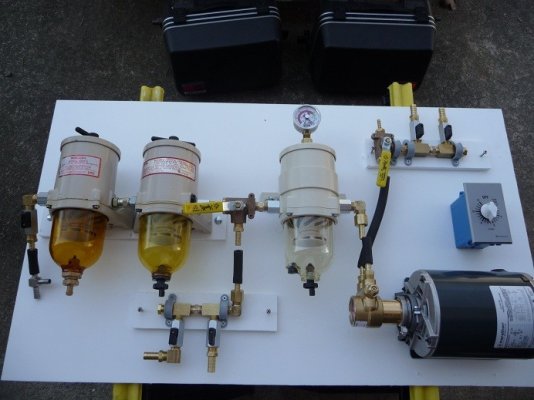
Anyway, the bottom left is the tank intake manifold with a new exit for the genset fuel supply. I will be adding a small dedicated Racor filter for it. Follow it up to an "L"-port valve that selects the multi-stage system to the engine OR to the polishing filter. Out of that Racor to a CORRECTLY oriented pump and on to the output manifold. The output manifold now begins with an "L"-port ball valve to select fuel from the polishing circuit or from the engine injector pump return ONLY. There is now no chance of pressurized fuel getting to the injector pump! The manifold, as with the input manifold, allows for future "day tank" expansion.
The NUMBER ONE problem that needs addressing will be leveling off of all the ports of the Racor filters (as pictured in the 5th picture below). I suppose I can plane down some shims out of teak or starboard. We'll cross that bridge later.
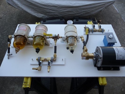
The last picture is of all the leftovers after the slim-down!

So... What do you think of the new mock-up?
Tom-
-- Edited by GonzoF1 on Sunday 13th of February 2011 07:39:14 AM
Well, well, well... Thanks to the engineering styling's of a regular member here (I'll let him come out of the closet if he wants to), I have been re-inspired to take the project in a new direction. So, with that, I guess a new thread would be in order to give new eyes to the goings-on.
Picture 1 below was sent to me via email.
I studied it long and hard. I almost dismissed it, but gave it a second look today and decided to COMBINE the two ideas. My biggest problem was ego. I was proud of what I had done (with all your help) and didn't want to throw out all the work I had done. All the hours spent at the Grainger website would have seemed wasted. I also feel like Spring is coming and I don't want to still have the system in bits when it happens. BUT... when I dragged it all into the bilge today, I realized it could be better. So, I took it out, took it COMPLETELY apart, and set to work.
A few things became clear to me:
a) There is just too much rubber in this rig.
b) There is just too much brass in this rig.
c) There were too many ways to get the setup wrong during use. (ie: pressured fuel to the injector pump)
d) It's not a bad idea to still be able to supply fuel to the genset while polishing.
e) I could flip the 3rd filter in its mount for a tighter install.
f) I decided to scrap the bypass of the polish filter. I figured I would use fuel xfer so little, filtering it as I did it would never be a bad idea.
Basically, in Rick's picture below, he is using three-way ball valves with a "T" port for tank selection on the input and output. Good idea for sure, but two things stopped me from using them. First, those vavles are about $50 each
Anyway, the bottom left is the tank intake manifold with a new exit for the genset fuel supply. I will be adding a small dedicated Racor filter for it. Follow it up to an "L"-port valve that selects the multi-stage system to the engine OR to the polishing filter. Out of that Racor to a CORRECTLY oriented pump and on to the output manifold. The output manifold now begins with an "L"-port ball valve to select fuel from the polishing circuit or from the engine injector pump return ONLY. There is now no chance of pressurized fuel getting to the injector pump! The manifold, as with the input manifold, allows for future "day tank" expansion.
The NUMBER ONE problem that needs addressing will be leveling off of all the ports of the Racor filters (as pictured in the 5th picture below). I suppose I can plane down some shims out of teak or starboard. We'll cross that bridge later.
The last picture is of all the leftovers after the slim-down!
So... What do you think of the new mock-up?
Tom-
-- Edited by GonzoF1 on Sunday 13th of February 2011 07:39:14 AM