Wil
Senior Member
- Joined
- Jul 8, 2013
- Messages
- 187
- Location
- US
- Vessel Name
- Gone Walkabout
- Vessel Make
- 1999 KadeyKrogen 39
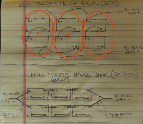
I'm swapping out my existing 12v house bank (six Trojan GC2s in 3P2S) for six FireFly L15+s in either (12v) 6S2P or 2P6S configuration.
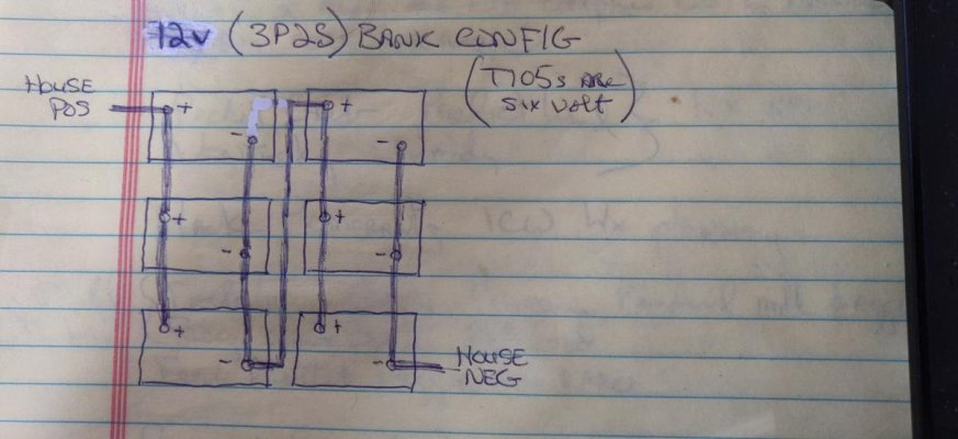
Background: FF L15+s are interesting in that each battery consists of 2 x 450Ah/2v cells that can be set up in either series or parallel configuration. This allows using the same six L15+s to set up either a 12v/900Ah or 24v/450Ah bank.
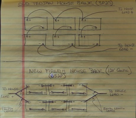
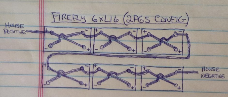
I'm looking for input here first on which 12v FF configuration (6S2P or 2P6S) to set up before I confirm with the factory, Schwab, etc. The 6S2P (see drawing of Old Bank and New Bank together) is much neater than 2P6S config (see Alternate configuration drawing), but maybe the 2P6S is better for some reason?
The batteries must go in the box as shown for the old T105 and new FF L15+ footprints to match.
Background: FF L15+s are interesting in that each battery consists of 2 x 450Ah/2v cells that can be set up in either series or parallel configuration. This allows using the same six L15+s to set up either a 12v/900Ah or 24v/450Ah bank.
I'm looking for input here first on which 12v FF configuration (6S2P or 2P6S) to set up before I confirm with the factory, Schwab, etc. The 6S2P (see drawing of Old Bank and New Bank together) is much neater than 2P6S config (see Alternate configuration drawing), but maybe the 2P6S is better for some reason?
The batteries must go in the box as shown for the old T105 and new FF L15+ footprints to match.
 . The other loads (fridge, pumps, radio, lights, etc.) are nominal.