Sizing a circuit

The friendliest place on the web for anyone who enjoys boating.
If you have answers, please help by responding to the unanswered posts.

angus99

Guru
Joined
Feb 19, 2012
Messages
2,742
Location
US
Vessel Name
Stella Maris
Vessel Make
Defever 44
I’m installing a new convection oven and induction cooktop and just want to idiot-check the electrical requirements.

Each requires a 15-amp breaker if they are on a dedicated circuit. Would I be safe in running a single circuit—wire sized for the combined maximum load—and protecting it with a 30-amp (or whatever) breaker?

I’m guessing this would work since the Empress stove I removed had both ovens and burners and all could be used simultaneously on the same circuit.

I would also make this circuit GFCI.

Thanks in advance.
 
I would not recommend combining the circuits. The breaker would not be sized properly for a single use load, i.e. Just the Oven, or Just the cooktop.

In the event you had an issue with just the cooktop, the breaker would be twice the recommended size of the manufacturer.

If you decide you don't want to use both at the same time, you could install a single 15amp breaker for both. If you try to use both, you will trip the breaker, but you are protected.

Recommend you put each on its own circuit.
 
Could he have a single 30a line, with a 15a fuse on each appliance?
 
The circuit breaker is to protect the wire. If you run the appropriate wire size then a single 30a breaker is acceptable. However, since the appliances are likely using smaller guage wire, it might be more appropriate to have a junction near the appliances were two 15a breakers are added to protect the appliance wire.
 
The circuit breaker is to protect the wire. If you run the appropriate wire size then a single 30a breaker is acceptable. However, since the appliances are likely using smaller guage wire, it might be more appropriate to have a junction near the appliances were two 15a breakers are added to protect the appliance wire.
This is what I would do, if easier and cost effective, if not run 2 lines.
 
I’m installing a new convection oven and induction cooktop and just want to idiot-check the electrical requirements.

Each requires a 15-amp breaker if they are on a dedicated circuit. Would I be safe in running a single circuit—wire sized for the combined maximum load—and protecting it with a 30-amp (or whatever) breaker?

I’m guessing this would work since the Empress stove I removed had both ovens and burners and all could be used simultaneously on the same circuit.

I would also make this circuit GFCI.

Thanks in advance.

That begs the question, how are the appliances connected? If they're plugged in to a GFCI receptacle, then the 30A circuit exceeds the rating of the receptacle, as well as the connections for the individual appliances.


What's the objective with a single circuit? Sounds like a solution in search of a problem. If you run a 30A subfeed, then you have 3 breakers, 2 of which are buried somewhere in a panel box that's just redundant.

If you're going to run cable, it won't take that much more effort to run two than it will one. Run #12, make it 2- 20A circuits, use 20A rated receptacles, then it's done without someone down the line scratching their heads trying to figure out what went on before.

You'll have capacity for your planned appliances plus some extra. As others posted, the overcurrent device protects the wiring. Unless the appliance is hard wired, I'd provide a conventionally wired, uncomplicated source.
 
Last edited:
Could he have a single 30a line, with a 15a fuse on each appliance?

The circuit breaker is to protect the wire. If you run the appropriate wire size then a single 30a breaker is acceptable. However, since the appliances are likely using smaller guage wire, it might be more appropriate to have a junction near the appliances were two 15a breakers are added to protect the appliance wire.

I was thinking the same about wire vs device protection.

The separate breakers nearby might work. I just need to find a spot for the subpanel that doesn’t require removal of the cooktop. :D

Thanks, all.
 
All of the above comments are valid. If the stove can be wired so that the 10 gauge, 30A rated wire is connected internally to the stove then it should be fine. But if you wire 10 gauge to two 14 gague cords in an external junction box, then no.


No wire less than 10 gauge can be exposed externally if it is protected by a 30A breaker. Wires internal to the stove are ok, since any fault that causes overheating, insulation melting, and a fire will be contained in a metal box, ie the stove.


David
 
That begs the question, how are the appliances connected? If they're plugged in to a GFCI receptacle, then the 30A circuit exceeds the rating of the receptacle, as well as the connections for the individual appliances. What's the objective with a single circuit? Sounds like a solution in search of a problem. If you're going to run cable, it won't take that much more effort to run two than it will one. Run #12, make it 2- 20A circuits, use 20A rated receptacles, then it's done without someone down the line scratching their heads trying to figure out what went on before. As others posted, the overcurrent device protects the wiring. Unless the appliance is hard wired, I'd provide a conventionally wired uncomplicated source.

Steve, I neglected to mention that a single circuit to the old Empress 3-burner/oven already exists. Wiring, is sized to 40 amps. Obviously, I’d like to avoid running a second dedicated circuit.
 
Steve, I neglected to mention that a single circuit to the old Empress 3-burner/oven already exists. Wiring, is sized to 40 amps. Obviously, I’d like to avoid running a second dedicated circuit.
I get it, then a case could be made for using that circuit as a sub-feed to a small panel with appropriate breakers for the 20A or 15A circuits. Check on the requirements for that subfeed panel. It should at least be accessible so if one of the breakers opens, it will be evident without hunting.
 
Steve, I neglected to mention that a single circuit to the old Empress 3-burner/oven already exists. Wiring, is sized to 40 amps. Obviously, I’d like to avoid running a second dedicated circuit.

Then maybe the easiest path would be to put in a sub panel with 2 15 amp breakers near the oven.
 
Then maybe the easiest path would be to put in a sub panel with 2 15 amp breakers near the oven.

Agree. A Blue Sea subpanel is on order.

Thanks.
 
I like Blue Seas stuff. Any problem with ordering from them since the fire?
 
Almost everyone says the panel I need is back-ordered. I found one allegedly in stock somewhere and ordered it but I’m half-bracing for bad news. On the other hand, I ordered a BlueSea fuse block a couple weeks ago and it was available everywhere. :confused:
 
Sub Panel wiring

I agree with the sub panel approach. However grounds and neutrals from the two circuits must be isolated from each other in the new sub panel and all the way back to the main panel. This avoids Ground loops, Ground faults, and other
undesirable features.
 
I agree with the sub panel approach. However grounds and neutrals from the two circuits must be isolated from each other in the new sub panel and all the way back to the main panel. This avoids Ground loops, Ground faults, and other
undesirable features.

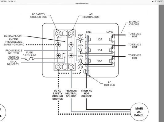
Really? BlueSea doesn’t seem to have designed their sub panels that way.
 

Attachments

  • 70DD4B12-9EA8-4D0F-B014-4B018C54B0A6.jpg
    70DD4B12-9EA8-4D0F-B014-4B018C54B0A6.jpg
    96.6 KB · Views: 35
Isolation techniques

The isolation of grounds and neutrals is accomplished by inserting an insulator under the neutral bus bar to prevent it from being in common with the ground busbar and sub panel itself. The panel might include this component. Usually all you have to do is remove the neutral busbar screws and slip the insulator under it and retighten the screws. Its made this way because the panel can also serve as a Main Panel where the neutrals and grounds are normally common.
 
Neutral and ground should not be connected at the main panel unless the source of power is aboard the boat, the genset or inverter. If you are plugged into shorepower then the neutral and ground must be segregated. With the new GFI dock power if you have neutral and ground connected at the main panel it will immediately trip the breaker on the dock.
 
I have an inverter and an isolation transformer installed. My recollection (without a refresher on this) is that the isolation transformer totally eliminates the neutral connection with shore power. We have plugged in to dozens of shore power pedestals without a problem.
 
The isolation of grounds and neutrals is accomplished by inserting an insulator under the neutral bus bar to prevent it from being in common with the ground busbar and sub panel itself. The panel might include this component. Usually all you have to do is remove the neutral busbar screws and slip the insulator under it and retighten the screws. Its made this way because the panel can also serve as a Main Panel where the neutrals and grounds are normally common.

Maybe I misunderstood you. Thought you were saying the neutral and ground wires needed to be run from each device directly back to the main panel, bypassing the subpanel.

Does anyone see a problem with the wiring diagram above from BlueSea?
 

Latest posts

Back
Top Bottom