questions from crimping wires

The friendliest place on the web for anyone who enjoys boating.
If you have answers, please help by responding to the unanswered posts.

paulga

Guru
Joined
May 28, 2018
Messages
972
Location
United States
Vessel Name
DD
Vessel Make
Marine Trader Sundeck 40'
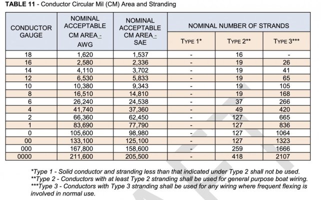
I spead out to count the strands of the existing wires. the existing one has 7 thick, rigid strands, comparing with the 12g wire that has 19 thin, more pliant strands. so the existing wires are 14awg?

Image_20240318080325.jpg

though it has 7 strands, each strand is thick. folding the wires double will not fit through a yellow connector wire barrel. I don't have blue connectors, so I crimped the wire into a yellow connector. this is what it looks like - there seems to be some spaces among the wires, but I did pushed the crimper as far as I could. in the end it was working, but I think the connections could be denser.

Image_20240318080331.jpg

this is the connections that I made:

Image_20240318080342.jpg

vs the originally completed wire connectors. were these done with a high capacity crimper?

Image_20240318081834.jpg
 
Strand count has nothing to do with wire gauge. It’s the total circular mils that determine gauge.
Your crimps are ok, the originals are from a different crimper for sure.
After you crimp, just make sure the strands are secure and there’s no movement inside the fitting.
 
Strand count has nothing to do with wire gauge. It’s the total circular mils that determine gauge.
Your crimps are ok, the originals are from a different crimper for sure.
After you crimp, just make sure the strands are secure and there’s no movement inside the fitting.

Thanks.
the crimped connection felt secure and holding well.
 
Strand count has nothing to do with wire gauge. It’s the total circular mils that determine gauge.
Your crimps are ok, the originals are from a different crimper for sure.
After you crimp, just make sure the strands are secure and there’s no movement inside the fitting.

Yep!

Also make sure the the seam of the connector is in the U of the crimper. The fork part goes to the back side of the tool.

https://www.homedepot.com/p/Klein-Tools-Crimping-and-Cutting-Tool-for-Connectors-1005SEN/100352095
 
the wires were likely from 1980s Taiwan. that is considered a quality period

the crimper I was using is exactly the one linked in #4
 
We all have to deal with whatever is in out boats already, and there are time when we all need to do whatever is necessary to get something to work. But whenever possible, you really should use correctly sized connectors. Unless that's 12ga wire, the yellow connectors are too big. You got it to work, it seems, but it's not as secure or electrically sounds as it should/could be.

There also are stranding requirements for wire used in boats, as shown in this table from the ABYC E-11 Electrical Standard. It looks like the "old" wire that you were working with does not meet spec. I don't know if that's original to the boat, or a previous retrofit. The newer 19 strand wire is correct.
 

Attachments

  • stranding.jpg
    stranding.jpg
    162 KB · Views: 28
Thanks.

it's not possible to know if the wire was added at some point. the previous owners did not leave a journal that documents when er outlet 1 was added, when and how outlet 2 was decommissioned.

when other, more urgent projects are done, I would start tracing wire back and replace it to the standard.


We all have to deal with whatever is in out boats already, and there are time when we all need to do whatever is necessary to get something to work. But whenever possible, you really should use correctly sized connectors. Unless that's 12ga wire, the yellow connectors are too big. You got it to work, it seems, but it's not as secure or electrically sounds as it should/could be.

There also are stranding requirements for wire used in boats, as shown in this table from the ABYC E-11 Electrical Standard. It looks like the "old" wire that you were working with does not meet spec. I don't know if that's original to the boat, or a previous retrofit. The newer 19 strand wire is correct.
 
For the best & most complete info on wire terminations CMS (Commercial Member here on TF)
Has a DIY website with great articles. Here is one but there care others on batty cables, etc.

https://marinehowto.com/marine-wire-termination/

Quality crimps and crimper matter. Also for connecting different ga wires you can get crimps with different ends... sort if like a pipe reducer.
 
the wires were likely from 1980s Taiwan. that is considered a quality period

the crimper I was using is exactly the one linked in #4

I keep that same Klein crimper in my tool bag. It’s a quality tool. You used the correct part of the tool for insulated fittings. The u shape is for non insulated. And as has been mentioned, the split in the crimp goes inside the u portion.
Insulated fittings go closest to the hinge.
I use crimp fittings with built in heat shrink protection on them. It’s an extra step but I feel like it’s worth it. Nothing wrong with the 3m ones you’re using, but you can also get those in non insulated and use your own heat shrink to seal them. Just an option.
 
Greetings,
Ms. p. Your post #9: "...replace it to the standard." AYBC is NOT a standard. They have developed a series of suggestions that the boating industry has agreed upon for new boat builds as being safe. There is no need IMO to replace your wiring with new unless it is too small a gauge, is damaged in some way or is inappropriate for marine use (solid house type wiring). Tinned wire is recommended but NOT necessary to meet official standards.


I stand to be corrected.
 
Last edited:
I keep that same Klein crimper in my tool bag. It’s a quality tool. You used the correct part of the tool for insulated fittings. The u shape is for non insulated. And as has been mentioned, the split in the crimp goes inside the u portion.
Insulated fittings go closest to the hinge.
I use crimp fittings with built in heat shrink protection on them. It’s an extra step but I feel like it’s worth it. Nothing wrong with the 3m ones you’re using, but you can also get those in non insulated and use your own heat shrink to seal them. Just an option.

i was crimping the same as the below screenshots. so i didn't understand "the fork part in the crimp goes inside the u portion"?


Screenshot 2024-03-18 105050.jpg

Screenshot 2024-03-18 105112.jpg
 
Here is the Molex crimping guide I used at work to teach operators how to inspect crimps. Enjoy!
 

Attachments

  • Molex Crimping Guide.pdf
    991.2 KB · Views: 97
Just buying a random crimper - even a ratcheting one, and crimping random terminals does not guarantee a good crimp. The Molex guide covers double crimps pretty well, but does not mention the nylon insulated ones that are common on boats. These crimp differently and require different jaws to crimp properly without compromising the nylon jacket.

I ratcheting crimper gives the impression of a good crimp without guaranteeing one. To do that you need to adjust the ratchet stop to the wire and terminals being used. Almost no one in the boating industry does this. The cheap and quick way is simply to pull - hard - on the finished crimp. An idea crimp will pull test to nearly the strength of the wire. A bad one will pull off easily. A really bad one can be felt as tiny unrestricted movement of the terminal relative to the wire.

If you are doing a lot of these, it is worth crimping some test terminals, then sawing through them to look at the cross section, adjust the crimper (or your hand pressure) as needed. This Amp guide is a little more directed at insulated terminals. Amp has several other guides of a more technical nature.

Heat shrink covered terminals are a whole different animal.

Yeah, I own about 15 different crimpers :)
 
I keep that same Klein crimper in my tool bag. It’s a quality tool. You used the correct part of the tool for insulated fittings. The u shape is for non insulated. And as has been mentioned, the split in the crimp goes inside the u portion.
Insulated fittings go closest to the hinge.
I use crimp fittings with built in heat shrink protection on them. It’s an extra step but I feel like it’s worth it. Nothing wrong with the 3m ones you’re using, but you can also get those in non insulated and use your own heat shrink to seal them. Just an option.

I think "the split in the crimp goes inside the u portion" means the same as "place the divot against the non gap end of the wire barrel" (for non insulated connectors)

Screenshot 2024-03-18 160806.jpg

here is the video source at 3:13
 
I think "the split in the crimp goes inside the u portion" means the same as "place the divot against the non gap end of the wire barrel" (for non insulated connectors)

View attachment 146466

here is the video source at 3:13

Exactly. I like the way non insulated crimps are done. Very secure. Cover with heat shrink for extra protection.
It took me a long time to warm up to using the insulated crimp portion of the crimper jaws, but when done properly it’s just fine.
Well done with your project!
 
@RT_Firefly #13:
Ms. p. Your post #9: "...replace it to the standard." AYBC is NOT a standard. They have developed a series of suggestions that the boating industry has agreed upon for new boat builds as being safe.

The ABYC Standards are, in fact, Standards. They are the minimum standards for recreational boating to provide a safe boat.

They are not enshrined in law as are the ISO standards that support the Recreational Craft Directive (RCD) but there is an active ongoing project to harmonize the ABYC Standards with the ISO Standards. Legally, many of the ABCY Standards are referenced and included by reference in the Code of Federal Regulations.

Be that as it may, when a surveyor performs a pre-purchase, insurance or damage assessment survey, the reference document used in the USA, and elsewhere, is the ABYC Standards.
 
OP:
I have upgraded many older boats with Type 2 (heavy stranding) legacy wire throughout the boat. Rather than rewiring the boat, which is cost prohibitive, and to improve reliability of the wiring system I have used the following process:
  • Re-terminate the legacy wiring behind the panel and at each major electrical component with ring terminals using a double anvil ratcheting crimping tool.
  • Land the re-terminated conductors on properly sized terminal strips.
  • Run new Type 3 (fine stranding) 105C Boat Cable from the new terminal strips to their respective breakers, fuses, switches, etc.
  • Inspect, as much as possible, the legacy wiring throughout the boat for breaks in the insulation, aging insulation that has lost integrity, chafe points, etc.

The advantage of this process is that it upgrades the maintainability and the safety of the legacy electrical systems and minimizes cost.
 
I ratcheting crimper gives the impression of a good crimp without guaranteeing one. To do that you need to adjust the ratchet stop to the wire and terminals being used....


Could you elaborate on that adjustment process?


I've been using one of these Ancor double ratchet units for about 15 years and was starting to wonder if there was a limit to its service life.
https://www.ancorproducts.com/en/p/703030
 
My understanding is that it is perfectly acceptable in the eyes of ABYC to use Type 2 (larger diameter individual strands but fewer of them) wire for general purpose wiring on a boat.

Type 3 wire (all stands 0.010” in diameter and many more than Type 2 wire) is required only in locations where frequent movement is encountered, like engines, or motors on isolators.

Further, Tin plated wire is not required by ABYC and the Tin itself does not improve the conductivity of the wire.

CharlieJ, please advise if my understanding is correct.

See post #7
 
Do the examples show terminals without integral heat shrink to illustrate the proper location of the crimp, or because terminals without integral heat shrink are now out of vogue or out with ABYC?
 
@luna # 23: Absolutely correct. However, Type 3 is far, far easier to work with, especially for wire AWG 4 and larger.

BTW, ABYC requires the use of Type 2 (@ least AWG 8) wire I in TBW bonding system.
 
Based on my experience of corroded non tinned copper wire on a previous boat, I switched to using tinned wire for all new work and retro and repair work. Does the tinned wore have advantages? What would you use?

For me, I have found the ratchet style of crimper to be more consistent.
 
I only use tinned wire. The extra cost is negligible and the benefits are great, IMO.
 
Data overload to be sure, however, here's a bit more. As a former marine electrician I've written about and blogged on this subject many times. These guides may be helpful.

Crimping Etiquette – Editorial: CO Poisoning Misinformation | Steve D'Antonio Marine Consulting

Recently released

The coarse strand wire is not ideal, the one with more strands does meet ABYC standards (the fewer does not), as Tanglewood noted, however, Type 3 fine strand wire is preferable for marine applications.
 
One other tip I'll toss in is with double crimp tools that also crimp around the cable insulation for strain relief, such as the ratcheting one in Steve's video, you need to make sure to put the terminal into the crimper the correct way.

The larger of the two crimps is for the strain relief crimping on the insulated wire, the smaller is for the crimp on the stripped wire. Different crimpers are marked differently, for my older Ancor tool you feed the wire into the terminal from the side with the colored dot on. That is opposite to the example in Steve's video using a different tool.
 
Last edited:

Latest posts

Back
Top Bottom