Please explain this shunt

The friendliest place on the web for anyone who enjoys boating.
If you have answers, please help by responding to the unanswered posts.

dhays

Guru
Joined
May 26, 2015
Messages
9,045
Location
United States
Vessel Name
Kinship
Vessel Make
North Pacific 43
I have a Xantrex Linklite monitor on my boat. They come with a 500A-50mV shunt. Reading the manual notes I see that it is important for the twisted wires to be connected.

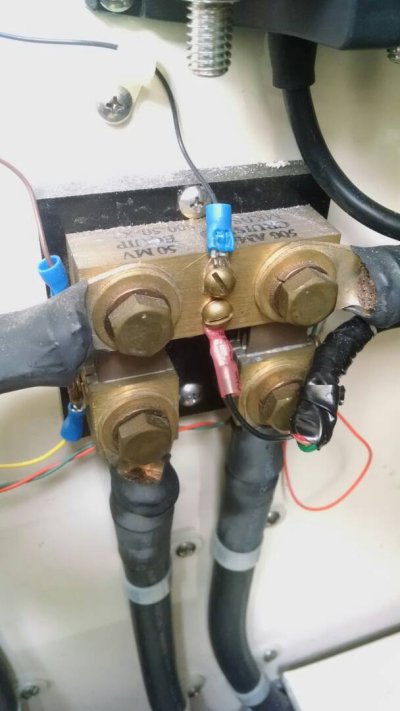
What confuses me is that this is the shunt that I have. It looks like a double shunt. Why, I don't know. The bottom posts are for the battery negative terminals the upper ones should be for the feed to the negative buss bars.

Anyway, why two? I haven't been able to find any double shunts anywhere. IMG_20170617_163639931.jpg
 
Maybe designed for dual-alts or a two-bank setup? Are all those multiple small wires attached to measure different circuits?

It's not size, I've got a 1000A shunt for Bogart Prometric but it's just one massive block.

They're pretty simple devices, so maybe the mfg had an oversupply of Manganin alloy*plates of a certain size and just designed around it?
 
Double check the wires, if both bottom wires are negative battery, don't think it would measure all the draw.

Ted
 
The shunt is from a link 20 or a link2000 monitor system which looked at two battery banks. all of the wiring are grounds. the cables on the top of the shunt go to the loads. Main panel, Inverter ect. Each of the two lower cables run to a different battery bank. one may have been the engine or start bank & the other would be the house.
Most likely the link unit failed, and was replaced with the LinkLite unit which reads only one battery.
 
Maybe designed for dual-alts or a two-bank setup? Are all those multiple small wires attached to measure different circuits?

It's not size, I've got a 1000A shunt for Bogart Prometric but it's just one massive block.

They're pretty simple devices, so maybe the mfg had an oversupply of Manganin alloy*plates of a certain size and just designed around it?


It appears that the shunt on the left is for the Xantrex Linklite. I have no idea what the shunt on the right is for. I need to see if I can trace those wires.
 
The shunt is from a link 20 or a link2000 monitor system which looked at two battery banks. all of the wiring are grounds. the cables on the top of the shunt go to the loads. Main panel, Inverter ect. Each of the two lower cables run to a different battery bank. one may have been the engine or start bank & the other would be the house.
Most likely the link unit failed, and was replaced with the LinkLite unit which reads only one battery.


That makes the most sense. Thanks a lot. It may be that the other shunt was for the engine start battery. Still could be as I have no idea where it goes. The load cable on the upper right goes forward, likely to the engine start battery. The upper left load cable goes to the neg buss bar that supplies the negative for all house loads and thrusters.

The reason I am looking at it is that I would like to add another battery banks negative to the same posts as the house bank negative. My thought is that this would then count all amps from both banks combined.

That is only a guess however as I really don't know how all this stuff works.
 
Last edited:
Those two little taps look to me like they are going to measure the same potential. Not sure they would measure anything.
 
Those two little taps look to me like they are going to measure the same potential. Not sure they would measure anything.


Yeah, those are odd. The central tap is the ground for the ACR. Not sure what the bottom one goes to. The battery monitors are connected on the sides, hard to see in the pictures.
 
The shunt is from a link 20 or a link2000 monitor system which looked at two battery banks. all of the wiring are grounds. the cables on the top of the shunt go to the loads. Main panel, Inverter ect. Each of the two lower cables run to a different battery bank. one may have been the engine or start bank & the other would be the house.
Most likely the link unit failed, and was replaced with the LinkLite unit which reads only one battery.

BTW Welcome to TF. Marine electric?:confused:
 
Page 33-34 has the diagram. I wasn't able to copy/paste.


Library Archive


That looks like it. I'm not awake enough to climb down and look at that panel but from memory, the twisted pairs connected to the shunt match the colors of wires in the diagram.

Thanks a lot!
 

Latest posts

Back
Top Bottom