OP
OP
tiltrider1
Guru
- Joined
- Aug 2, 2017
- Messages
- 4,352
- Location
- Pacific North West
- Vessel Name
- AZZURRA
- Vessel Make
- Ocean Alexander 54
This is a follow up.
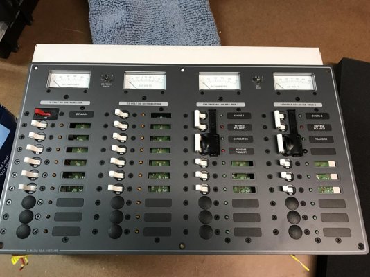
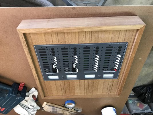
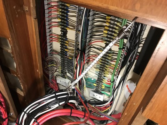
After discussions with an Electrical Engineer at Magnum and multiple posts on TF, I became convinced that I had possibly misplaced a neutral between the inverter side of the panel and the non inverter side. I pulled off and identified every neutral wire. Finally I came to one neutral wire that was both causing the problem and could not be identified. Everything on the boat is working and working correctly with the ELCI.
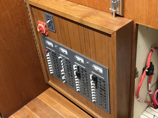
I do however, still have this one white wire that I can’t identify. For now it’s capped and labeled. Maybe some day we will identify it. There are two breakers on the panel that are not identified and one that was decommissioned. I am not certain if this is a related neutral and have no easy way to identify this.
In the mean time I’m happy to have a new inverter and a properly functioning ELCI.
After discussions with an Electrical Engineer at Magnum and multiple posts on TF, I became convinced that I had possibly misplaced a neutral between the inverter side of the panel and the non inverter side. I pulled off and identified every neutral wire. Finally I came to one neutral wire that was both causing the problem and could not be identified. Everything on the boat is working and working correctly with the ELCI.
I do however, still have this one white wire that I can’t identify. For now it’s capped and labeled. Maybe some day we will identify it. There are two breakers on the panel that are not identified and one that was decommissioned. I am not certain if this is a related neutral and have no easy way to identify this.
In the mean time I’m happy to have a new inverter and a properly functioning ELCI.