fryedaze
Guru
- Joined
- Sep 4, 2011
- Messages
- 1,721
- Location
- USA
- Vessel Name
- Fryedaze
- Vessel Make
- MC 42 (Overseas Co) Monk 42
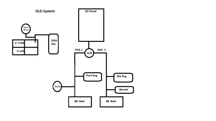
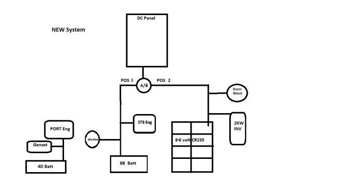
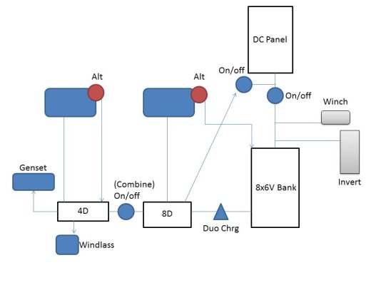
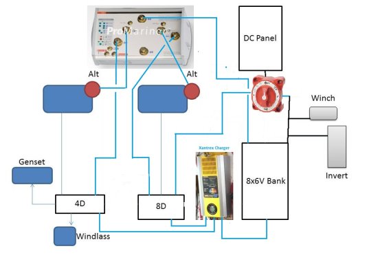
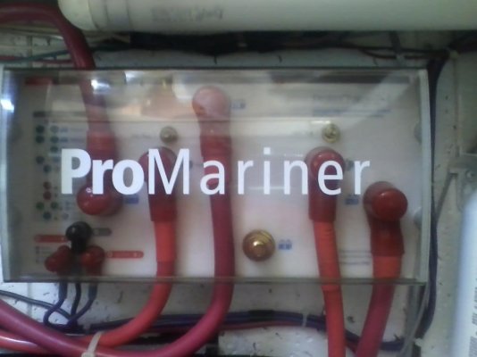
I am looking for feedback on my recent playtime in the engine room. I recently had a 6 volt battery fail and then this week my Stb 8D start/house battery fail. I have made changes to the distribution and would like some feedback if I am off base on my thinking. I intend to run the system in postion 2 on the A/B switch so that everything is run off the 8 new 6 volt batteries in the house bank. The old system was run in "Both" on the A/B switch. I replace the failed 8D with a 4D to save my jewels  . Let me know if you see flaws in this.
. Let me know if you see flaws in this.