Need more space on the positive terminal of house bank

The friendliest place on the web for anyone who enjoys boating.
If you have answers, please help by responding to the unanswered posts.

PMF1984

Guru
Joined
Sep 10, 2016
Messages
637
Location
United States
Vessel Name
Wanderer
Vessel Make
Pilgrim 40
I am adding to my house bank so I need to make an additional connection to the positive terminal of my existing battery.

Right now there is a cable coming off that terminal going to a buss bar, a cable for the ACR, and a cable for the solar panels. There is no more space on the terminal stud.

I remember seeing some solutions for this on an earlier string, maybe last year, but can’t locate it.

Any suggestions are welcome.

John
 
It's not clear what you're adding, but can you add whatever it is to the positive bus bar?
 
It's not clear what you're adding, but can you add whatever it is to the positive bus bar?


Sorry about that. Now I have 2 Trojan T-105 batteries in series. I want to add another 2 T-105’s (parallel hook-up) to double bank capacity. So between the two battery sets I need to go with a neg-neg connection and a pos-pos connection.

I can either move something to the buss bar or add to the possible terminal connection capability.

The solar guy told me I have to have the solar input on the terminal. The Battery monitor rig instruction say it must be directly on the terminal.

Perhaps the ACR can be on the buss bar?

Or just add to terminal capacity.

John
 
You might be thinking about the Terminal Tamer available from boatsteer.com. They come in two sizes. I’ve not used them but they look pretty well made.

Brett
 
There is absolutely no problem shifting the pos and neg connections that you describe to the buss bars. The only one that requires some thought is the battery monitor's shunt. The best way is to place the shunt in between the battery terminal and the negative buss bar, wired with big, 1/0 or bigger wire. The positive connection from the battery monitor supplies power to it and also the DC reference voltage. A tiny bit of voltage drop between the terminal and the buss bar won't affect it at all.

Another consideration is fusing of the positive leads. If your DC wiring to the solar panel controller and the house DC panel is big enough, say 6 gauge, you can install a 100A fuse block in between the terminal and the buss and that will protect those circuits. Others like power to a bilge pump can be fused independently because the wire is too small to take 100A. But if you have a big inverter, that will take probably 200A, so maybe better to fuse each circuit independently.

Lots to think about, but in general relying on a buss bar for all connections is fine.

David
 
How about the second set of battys you are adding in parallel?
If you add the jumper can you move one or two other leads to the second bank Pos & Neg?
I believe the best practice is not to charge or draw from one batty (or series pair) in a parallel hook up. Best to run POS to batty (bank)1 & Neg to batty (bank)2
So you now have 2 Pos & 2 Neg terminals for connections
 
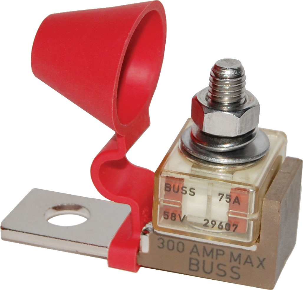
Something I did on my sailboat when I had the problem of not enough room on the battery terminal, was to use a terminal fuse block. Not sure if this is really kosher (check with someone who actually knows).

I need to add a fuse to protect some of the wires that were connected. I used a terminal fuse block to do that. This also gave me added connections. I simply combined a couple wires that needed similar fuse protection.

5191.jpg
 
Yes, that is a more compact version of a fuse block plus buss. Lots of room to stack multiple ring terminals. Not legal for AC but ok for DC I think. But in that case all wires connected to that terminal must be at least #8 gauge to be protected by the 75 A fuse.


David
 
The only one that requires some thought is the battery monitor's shunt. The best way is to place the shunt in between the battery terminal and the negative buss bar, wired with big, 1/0 or bigger wire.

...and NO OTHER grounds connected to the house battery negative terminal. Don't ask me how I know... :eek: :facepalm: :D

Blue Seas has bus bars with ample studs for multiple connections on a hot battery or ground terminal buss. Yes, the ACR/combiner can be connected to the bus bar instead of the battery terminal.

71OfbeNUPPL._SL1500_.jpg
 
Yes, that is a more compact version of a fuse block plus buss. Lots of room to stack multiple ring terminals. Not legal for AC but ok for DC I think. But in that case all wires connected to that terminal must be at least #8 gauge to be protected by the 75 A fuse.


Yes, the photo is just an example. You have to match like wire sizes so they are protected appropriately by the fuse.


BTW, BlueSeas also makes a double fuse terminal block which gives more room and allows for different fuse sizes for different size wires.

2151.png
 
I never knew about double fuse blocks. Great product. You can use a 200A fuse on one to feed an inverter, then maybe a 60A fuse on the other to feed the house panel, solar controller, etc with at least 10 gauge wire.


David
 
The solar guy told me I have to have the solar input on the terminal. The Battery monitor rig instruction say it must be directly on the terminal.


Wait... WHAT?!? I'd like to know the logic behind THAT statement. Either directly on the terminal or a dozen inches away via a 2/0 wire to a buss bar, it seems like there would be zero difference. Tell me I ain't crazy.
 
Tom:

Many technicians I have come accross in all fields only know what they were once told or maybe thought they read in a manual somewhere and either don't have the skills to analyze why and the use of good alternatives or may lack the inclination to do so. This must be one of those instances.


David
 
Last edited:
Wait... WHAT?!? I'd like to know the logic behind THAT statement. Either directly on the terminal or a dozen inches away via a 2/0 wire to a buss bar, it seems like there would be zero difference. Tell me I ain't crazy.


I agree with David. The “best” installation would be to connect them directly to the battery terminal. However, I have settled on the idea that there is a “best” way, a “good” way, and many ways that are “good enough”.

I’m pretty happy with “good enough” most of the time.
 
These are the cables I used when I upgraded both battery banks. Two pairs of group 31 AGM’s from East Penn Manufacturing (DEKA). Plenty of places to bolt on connections.IMG_0119.jpg
 
I agree with David. The “best” installation would be to connect them directly to the battery terminal. However, I have settled on the idea that there is a “best” way, a “good” way, and many ways that are “good enough”.

I’m pretty happy with “good enough” most of the time.

WHAT?

Not suggesting perfection?

you'll never last on here...... :)
 
As I age, and do really stupid things I never thought capable of when I was young and smart...


I am a big fan of all wiring going to a buss bar, and only single supply cabling on the batteries themselves.


When all those wires are disconnected at battery changing time.... and even one of them goes where it shouldn't...


I also agree with David, the number of idiot paid vendors and "technicians" who give out bad advice outnumber the good ones... when the solar craze has run its course, they'll be selling the next best wave of uncertainty to unsuspecting hobbyists...


RB
 
Big fan of bus bars. Take the multitude of cables out of the battery box and organize them on a bus bar. With a complicated boat one would need both a 3/8" and 5/16" stud bus bars for both positive and negative.

Also put in a shut off switch and fuse between the battery bank and the positive bus bar
"
 
On the bus bar, I like to bring the positive feed into the center of the bus bar rather than an end.
 
All my batteries have one wire coming off them, both + & -. THose wires go to a buss bar. Other than the one temperature probe for charging over temp protection there are no other connections to the actual battery.
I did that 30 +yrs ago and have never been sorry. My only regret is that the busses were not larger but they cleaned things up hugely.

Look at those busses from Blue Seas. Keep multiple connections at the busses, NOT the battery posts/terminals.

It was a mess like you described that almost caused a fire and why I went for the busses. Blue Seas and Ancor were not around so I built my own.

A couple years ago I added the fuse and holder pictured in post #7. Each of 3 house batteries has one on it at 100A.

If you use those fuses and holders then the actual feed wires between a buss and the batteries can be fairly long. I will suggest that if you go this route that with multiple parallel batteries to build the house bank that all the set of + leads are the same wire AND the same length. THe same is the case for the set of - leads.
Note though that the + & - sets do not have to be the same lengths.
 
Last edited:
Using a buss bar makes for the cleanest install and I agree is the best way to do it. That is how my current boat is setup. However, those terminal post fuses worked great on my last boat.
 
Wire new house bank with proper heavy marine interconnecting cable then with same cable equally to 2 blue sea buss bars. Connect all to pos and neg buss fusing as needed.
 
Since you really should have a fuse within 6" of the battery, there should be no connections directly to your batteries before that fuse, other than possibly a battery monitor with its shunt. All the batteries should be connected together as needed, then all other connections should be on a busbar or two after the fuse.
 
I never knew about double fuse blocks. Great product. You can use a 200A fuse on one to feed an inverter, then maybe a 60A fuse on the other to feed the house panel, solar controller, etc with at least 10 gauge wire.


David
I do exactly that. Previously the PO had everything (from 2/0 to #12 gauge) hooked directly to positive terminals with NO FUSES OR BREAKERS at all.
 
Since you really should have a fuse within 6" of the battery, there should be no connections directly to your batteries before that fuse, other than possibly a battery monitor with its shunt. All the batteries should be connected together as needed, then all other connections should be on a busbar or two after the fuse.

As far as I've seen, SOC Meter shunts are installed on the NEGATIVE lead and fuses are used on the POSITIVE lead.
 
never connect a bunch a wires to a battery post! look at the one on 'flywright`s post, and make your own! i made a set [pos/neg, 6 stainless bolts each] get some plastic, 3/8" thick, X 3" or 4" wide, X 10" long, so there is at least an inch or more between the bolts, counter sink the back side so the heads are flush, mount a foot or so away from the battery, connect to the battery with at least #2 or #4 wire...works great...clyde
 
Last edited:
Don't post here much, so a little hesitant to jump in the middle of this.
My back ground is heavily electrical. Not Marine. I ran the electrical department for a large utility power plant.
I concerned with some of the ratings, and lack thereof, being thrown around.
If you are going to attach the batteries to a bus. Which is the right way to do it. You need the proper size cable and bus.
If you double the bank size you need to make sure the old bus is rated for it.
The cabling from the batteries to the bus should be rated for at least double the ah rating of the batteries. If you Cable the batteries together first and then run to the bus. Which is okay, then the Cable to the bus should be double that.
We should be talking in the neighborhood of 1/0 and 2/0 cables not #8 or #6.
Anyhow just my 02.
Martin
 
martin, your right, i usually use 2/0 everywhere, but with the external battry connectors, i usually go by the number of connections, what they run, so i know how many amps are being used, and the distance from the battery! which is`nt very far, for the wire size i need, but it`s also wise to keep alll wires the same size, for the flow! when i was doing some wire corrections 25 yrs ago on our boat, we had a 100 amp alternator, with an isolated ground, the gnd was 1/4"!!! lots of stuff like that, that i changed for the better! also changed to a 160 amp leece nivelle...the newer model never goes over 14.1 volts!...clyde
 
Thanks for all your suggestions. I ended up with a big buss bar and hooking up everything to it (ACR, alternator, inverter/charger, solar panels).

Just some side notes. I thought that wire size was calculated on load, not available capacity. Adding two more batteries does not increase my load. (Although once you get more battery capacity, one is tempted to add some dohicky that increases load.)

West Marine new price match policy made it my go to place for all the materials. On the small stuff I just paid the posted price, but I price matched for the lugs and wire. They had the crimp tools at the store so I was able to make up all the heavy cables. (The closest WM is about a mile from the boat - so that has a bearing on it too.)

Again thanks for all the input.

John
 
Thanks for posting the final conclusion. Not many do.


Yes wire size is calculated to carry the desired current- ampacity but at the desired voltage drop which usually means increasing the wire size beyond the minimal ampacity size. Then fuse according to the maximum load required.


Also you don't need to add up the negative loads and the positive current inputs (solar, charger and alternator) and size accordingly. Typically it is just the negative loads that determines wire size.


David
 
Back
Top Bottom