More solar questions....

The friendliest place on the web for anyone who enjoys boating.
If you have answers, please help by responding to the unanswered posts.
Since this thread was already started I have a question about diodes. I notice yesterday that my diode at the solar panel was broke or blown. What size diode should I be using for one 120 watt solar panel? This is the second time over the last 5 years. The location it's in is not the best and out in the elements. Also how close does it need to be to the solar panel?
 
Since this thread was already started I have a question about diodes. I notice yesterday that my diode at the solar panel was broke or blown. What size diode should I be using for one 120 watt solar panel? This is the second time over the last 5 years. The location it's in is not the best and out in the elements. Also how close does it need to be to the solar panel?

If the diode is blown then you aren't getting any output from the panel, right?

Where is the diode? Usually they are in a junction box on the panel. But usually there is more than one, often four so that different sections of the panel are isolated to reduce the effects of shading.

A 120 watt panel has a maximum current output- Isc of about 8 amps. A ten amp diode should work fine if it is a single diode. If it is four then the current from each section is about 2 amps, so a 3 amp diode should work.

But small diodes are cheap. Here is a package of ten 10A diodes for less than $6.00- https://www.amazon.com/VNDEFUL-Mold...UTF8&qid=1525269280&sr=8-4&keywords=10a+diode

If you just have a single diode, put two 10A in parallel for redundancy and to keep the current low on each. Make sure you get the polarity right. If it is backwards you won't get any output from the panel.


David
Thanks David , I only have one in line and there is no junction box , it's close to the solar panel and out in the elements. After I install it can I heat shrink the diode and connections to help protect?
 
Last edited:
Thanks David , I only have one in line and there is no junction box , it's close to the solar panel and out in the elements. After I install it can I heat shrink the diode and connections to help protect?
I can see now why it needs the junction box. This is the way the PO had it installed . I'm going to pick up a junction box also. Thanks for the help.
 
If you have only one diode on only one panel, then you don't need it. Bypass it and connect the two wires with a heat shrink crimp connector.

You don't need it because with only one panel you don't need to worry about shading and the controller has a diode in it that protects from back feeding the panel at night.

David
Ok thanks, it’s just one panel . I didn’t know the diode was built into the controller. I’ll post a picture of my controller later. I’m pretty sure I have the manual as well .
 
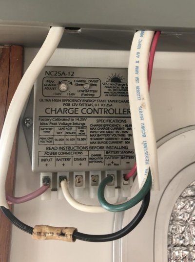
Here is my controller. I wasn’t able to locate the manual but I know I have one. I haven’t repaired the wire yet , had to do some painting on roof today . The boat is under cover .
 

Attachments

  • 80883563-5D6D-4458-A15E-3AC90BC56B8C.jpg
    80883563-5D6D-4458-A15E-3AC90BC56B8C.jpg
    102.4 KB · Views: 74
Yeah. Don’t use extra parts[emoji108] and if u do push 10amps thru a diode it likely needs a heat sink
 
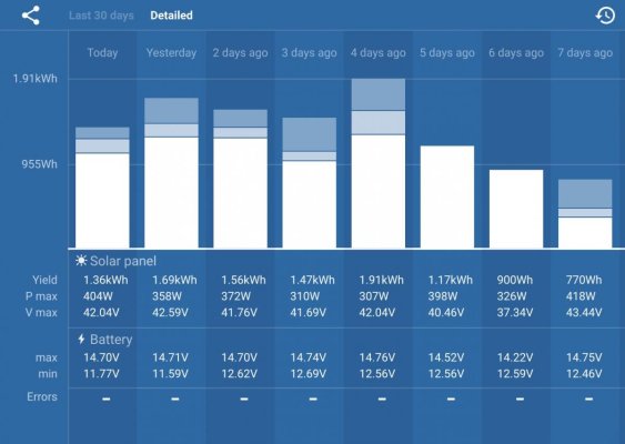
One of the things that I’m finding a but surprising is the max wattage that the solar panel is putting out according to the charge controller. This is a screen shot of the last week. We’ve had a few nice days, which means broken clouds underneath a high, thin overcast. Occasionally, the sun will shine through some blue however. The solar panel is rated at 365W. I didn’t really expect to get that very often. However, the charge controller thinks the panel is occasionally cranking out 400W.
IMG_0415.jpg
 
Question for the smart folks in the room. Because I’m back feeding the batteries, the voltage that the charge controller is putting out, is not the same as what the battery is getting. The difference that I’m seeing is between .15 and .20v. So, can I adjust the battery profile on the charge controller to account for this difference? In other words, my batteries should float at 13.4v and absorb at 14.7v. Can I set the charge controller to 13.55v and 14.85v to make up for the voltage loss>
 
The panels are usually rated at 77 deg temperature. If cold, they can put out somewhat more. If hot, a lot less. I've gotten about 5 KW out of my 4 KW roof system on a cold morning. There are also some panel to panel variations, the spec is supposed to be the minimum.

On your voltages, how are you determining them? a good DVM? or other monitors in the circuit? Is the charge controller a PWM or MPPT controller?

A DVM at the battery terminals is the most reliable, the DVM should be accurate and at the battery, transients are less likely to be measured.
 
Thanks for the replies. While not necessarily relevant to the question, here is more information.

Victron SmartSolar 100/30 charge controller back feeding into the electrical system from the DC panel in the Pilothouse. It is a MPPT controller that has an internal temperature sensor but it is located a ways from the batteries and generally the batteries will be either a few degrees warmer or colder than what the charge controller thinks. 365W rated solar panel. So far the max that the panel has put out is just over 400W.

The longer story... The reason the question was asked is that the Victron SmartSolar controller has built in bluetooth. Victron just release the Smart Battery Sense which is a bluetooth voltage and temperature sensor. I picked one up and installed it. Unfortuantely, while the SmartSolar Controller appears to be using a Class 2 bluetooth transmitter, the Smart Battery Sense appears to be using a Class 3 transmitter. It barely will give a 6’ range, not nearly enough to get from where the batteries are to where the charge controller is. So that $50 experiment was a bust.

However, I noticed that the voltage at the battery that the sensor was measuring was different than what the charge controller thought. How much difference seems to depend on the power being produced by the panel and how that compares to the drain on the batteries at the time. The range that I’ve seen has been .1v to .2v difference, with the battery showing less voltage than the charge controller thinks it has. That makes sense as there is a loss from the pilothouse to the batteries. The loss appears to be about 1.5%. I checked the Smart Battery Sense reading with a multimeter and it is accurate.

FWIW, my Magnasine charger/inverter must have a feed from closer to the battery because it agrees with the Smart Battery Sense. It only displays voltages in .1v increments but when the Smart battery Sense was reading 13.47 today the Magnasine display was bouncing between 13.4 and 13.5

Yes, I know that backfeeding is not idea. I know that I should have the charge controller close to the batteries. I know that I should have temperature and voltage sensing at the batteries. I’m sure I am doing all kinds of things wrong, however, my questions is given all the stuff I am doing wrong, can I compensate for that voltage drop by telling the charge controller to charge the batteries about .15v more than what they really need?
 
Dave-

My Victron 150-70 (or is it 70-150?) allows one to set both the bulk and float voltages and my guess is that yours also provides a similar feature. Check your manual. I also suggest that you check with your battery's manufacturer for their bulk and float recommendations.
 
I believe you can safely change the absorption voltage to compensate for the wiring loss. This may run the absorption rate a little too high as the batteries reach full charge - the charge current and therefore the wiring loss will drop. In float, there is presumable very little current going from the solar controller to batteries, so the two readings should be very similar when the batteries are fully charged. You would not want to set the charge voltage high to compensate for a wiring loss, but then have them sit fully charged at too high a float voltage.
 
Dave-

My Victron 150-70 (or is it 70-150?) allows one to set both the bulk and float voltages and my guess is that yours also provides a similar feature. Check your manual. I also suggest that you check with your battery's manufacturer for their bulk and float recommendations.


Yup it does. My batteries call for 14.7v absorb and 13.4v float. That is what I have the charge controller set for. However, the battery is only seeing about 14.55v and 13.25v. My question is can I just reset the charge controller to a higher value knowing there will be some loss of voltage at the battery?
 
I believe you can safely change the absorption voltage to compensate for the wiring loss. This may run the absorption rate a little too high as the batteries reach full charge - the charge current and therefore the wiring loss will drop. In float, there is presumable very little current going from the solar controller to batteries, so the two readings should be very similar when the batteries are fully charged. You would not want to set the charge voltage high to compensate for a wiring loss, but then have them sit fully charged at too high a float voltage.


That makes a lot of sense. Higher loss at higher amps and voltage (ie build and absorb) but lower loss at lower voltage and amps.

I can keep comparing the voltages to get a feel for what the losses actually are under various conditions.

I am looking at using a wired battery sensor. It will be a bit of a pain to run the wires however.
 
What you are describing is called "remote sense" in the power supply vernacular. It would account for most any wire V drop. However, I don't think 150mV is a significant drop in this application.
 
Yes and no.


Voltage drop is entirely dependent on the current flow. So at absorption conditions significant current is flowing and setting the voltage up a few tenths to compensate makes sense.

But at float conditions there is little current flowing and the voltage drop isn't anywhere near the .15-20 V that you noted (probably at medium/high current flow). So don't increase the float voltage.

Even better is a controller with remote battery voltage sensing like a Balmar alternator regulator.

David
 
I think you are worrying too much. You have a battery sensor with your Magnum Inverter charger, which will be close. Plus, you may get the voltage higher, but the amps will be lower as a result. I don’t think raising the voltage is going to change the end result as you probably don’t have enough hours of sunlight to affect the float charge. We often find we rarely get to higher absorb charges, due to the low amps into the battery vs those used real time.
 
I asked about temp earlier because you cannot conclude that the float volts you are reading at the batteries is necessarily wrong. You need to know the temp at the batteries and then ask the battery manufacturer for their float voltage-temp adjustment table (they should be able to give it to you for Absorption volts as well). Standard float (& absorption) voltages are usually given as at 20C (68F); at temps less than this, the Float voltage will be higher. You may in fact be spot-on where you are.
 
Yup it does. My batteries call for 14.7v absorb and 13.4v float. That is what I have the charge controller set for. However, the battery is only seeing about 14.55v and 13.25v. My question is can I just reset the charge controller to a higher value knowing there will be some loss of voltage at the battery?


Your controller adjusts for battery temp locally at the controller unless you have an optional temp sensor. This is why the controller should be close to the batteries. It may think your batteries are warm and be compensating voltage down a bit. Simple test for this is to go into the settings and turn off temp comp temporarily. Please don't adjust your absorption voltage up to compensate for voltage drop as once current declines you will be left charging at too high a voltage. If the controller is close to the bank voltage drop should be minimal..
 
Your controller adjusts for battery temp locally at the controller unless you have an optional temp sensor. This is why the controller should be close to the batteries. It may think your batteries are warm and be compensating voltage down a bit. Simple test for this is to go into the settings and turn off temp comp temporarily. Please don't adjust your absorption voltage up to compensate for voltage drop as once current declines you will be left charging at too high a voltage. If the controller is close to the bank voltage drop should be minimal..


Thanks Rod. Unfortunately, the controller is NOT close to the batteries so I am getting anywhere from 1%-1.5% voltage drop between the controller and the batteries. The the voltage at the battery is different than what the controller thinks it is.

Unfortunately, the Smart Battery Sense appears to use a Class 3 transmitter so it doesn’t have the range I need. Is there a wired temperature sensor that will work with the SmartSolar controller?
 
"The the voltage at the battery is different than what the controller thinks it is."

Might be time to start at both ends and disconnect the wires and measure resistance between the ends..

Sounds like a poor or dirty connection (Ground?) somewhere.
 
Unfortunately, the Smart Battery Sense appears to use a Class 3 transmitter so it doesn’t have the range I need. Is there a wired temperature sensor that will work with the SmartSolar controller?

I experience the same difficulty with the weak bluetooth signal with my recently installed Victron 100/50 Smart controller. If I am in the pilot house near the Color ControlGX/BMV712 display, I cannot get the bluetooth signal from the 100/50 controller which is located below, adjacent to the battery bank.

I even have installed the optional VE Direct cable between the controller and the ColorControl GX display and still cannot display the controller data on my phone unless I position myself exactly within the short range of the controller. The phone app has specific and helpful data that is not able to be displayed on the Color Control GX.

It's quite annoying to have purchased the Bluetooth capable controller and then to discover it be so limited in range. Definitely not usable except in inconvenient circumstances.

By the way, the Bluetooth connection with the BMV712 is perfect in all circumstances. Not helpful when wanting to read the more useful controller data, though. I hope Victron refine their firmware/software to correct these shortcomings. Or, perhaps it's user error! : )
 
Ahoy Dave, methinks you worry too much. Currently anchored Von Donup, waiting weather heading south, 5 weeks we have been gone, .8 hr on gen set, and have not plugged in anywhere. See Yah! Dan
 
Ahoy Dave, methinks you worry too much. Currently anchored Von Donup, waiting weather heading south, 5 weeks we have been gone, .8 hr on gen set, and have not plugged in anywhere. See Yah! Dan


I’m jealous Dan. I have never been in Von Donup but have wanted to go there. I won’t be able to make it that far North this year.
 
Thanks Rod. Unfortunately, the controller is NOT close to the batteries so I am getting anywhere from 1%-1.5% voltage drop between the controller and the batteries. The the voltage at the battery is different than what the controller thinks it is.

Unfortunately, the Smart Battery Sense appears to use a Class 3 transmitter so it doesn’t have the range I need. Is there a wired temperature sensor that will work with the SmartSolar controller?


The sensor is designed to be in close proximity to the controller & the controller close to the bank. If you can't make this happen you will be best to turn off temp compensation and accepth the volt drop, or beef up the wire gauge. Another option, if voltage getting to the battery terminals is lower than ideal, is to simply extend the absorption duration.
 
Dave: what are the loads under these tests? Is/are your fridge and/or freezer on? Are you on shore power? Your panels should be switched to off if you are on shore power. What happens while you are on shore power will be very different when you are away from the dock.

Jim
 
Back
Top Bottom