You are using an out of date browser. It may not display this or other websites correctly.
You should upgrade or use an alternative browser.
You should upgrade or use an alternative browser.
How do you get 30 amps from one 50?
- Thread starter ghost0070
- Start date
The friendliest place on the web for anyone who enjoys boating.
If you have answers, please help by responding to the unanswered posts.
If you have answers, please help by responding to the unanswered posts.
chiropaul
Senior Member
Hi,
A 30 amp cord should only be loaded 80-85%. What you are looking for is either a 50 Amp, 125v to two 30amp splitter cable, or depending on the pedestal you're connecting to, a 125/250volt to 2-30 amp splitter. The most important thing is the voltage at the dockside pedestal. In the first instance you would have a safe 80% of 50 amps, or about 40 amps to be divided between your 2-30's. The loads on your 30's would be determined by what you are powering in your panel.
The second instance, a 125v/250v set up would give you about 40 amps per cable, so you have to be careful not to draw that amount on a 30 amp connection.
Hope this helps.
ranger58sb
Guru
You just need something like this.
Or the 50A/250V version, as Paul mentions.
Ghost, one tidbit to know is that a 50A/250V source (for example) is actually making 100A available to a 50A or twin 30A boat; 50A on each of two legs. Hence the splitter takes one 50A leg and connects it to one 30A cord, the other 50A leg to your other 30A cord, e Voila!
-Chris.
MYTraveler
Guru
First I have ever heard that a 30 amp cord shouldn't have 30 amps flowing through it -- but should instead be limited to 80% (=24 amps) to 85% (25.5 amps). Seems like they should be limited by circuit breakers that break at those lower amperages.
psneeld
Guru
Never really heard a good source for that rule, but as connections become corroded, I am guessing the lower the load, the less heat buildup and less charring of the plugs.
But good cords and connections shouldn't be a problem carrying 30 amps.
But good cords and connections shouldn't be a problem carrying 30 amps.
The conservative rule of thumb for a quality electrical installation is not to challenge any of the circuit components to >80% of their rated capacity. For example, when I have the opportunity to design a system, the shore power circuit breaker for a 30A/125V service is 30/.8 = 37.5A and I specify a 40A DPCB. Of course all downstream wiring has to have >40A ampacity, but that is easily accomplished.
The marina's CB is usually a DPCB rated at 30A. They can do what they want to. I will be conservative on the boat.
The marina's CB is usually a DPCB rated at 30A. They can do what they want to. I will be conservative on the boat.
psneeld
Guru
Doesn't it matter whether you use 100 percent or 80 percent load CBe?
Then the question is does the boat really use 100 percent continuous load?
The power cord is rated to 60 amps, so if the boats panel CBs are 80 percent, not much chance of anything dangerous but nusuance trips..... unless corrosion and then isn't any amperage just a guess that can cause overheating?
Doesn't it matter whether you use 100 percent or 80 percent load CBe?
I don't understand your comment/question. I stated that the 80% rule of thumb is a conservative design parameter so as not to challenge any of the components in the circuit at their full rated value.
Then the question is does the boat really use 100 percent continuous load?
In Florida, in the summer...you betcha!
The power cord is rated to 60 amps, so if the boats panel CBs are 80 percent, not much chance of anything dangerous but nusuance trips
It is simply a design philosophy; don't operate anything continuously at full rated capacity. To that point, it is generally considered not prudent to operate a propulsion engine continuously at wide open throttle (100%), trust an anchor rode continuously at its breaking load limit (the safe working load is usually ⅓ the BLL), or run a genset at its full capacity.
I absolutely agree that there are 10s of thousands of boats operating nicely with a 30A shore power service that are passing through nearly a full 30A. I have chosen, as a design philosophy
to specify a 40A DPCB as the first shore power CB aboard (ELCI or panelboard).For example, when I have the opportunity to design a system,
Just food for thought.
skipper2
Member
Power cords and shore power
This conversation has missed the fact that shore power pedestals will have two phases of a 220 source to offer two 110v, 30 amp connections. Can't get more current without phase consideration.
This conversation has missed the fact that shore power pedestals will have two phases of a 220 source to offer two 110v, 30 amp connections. Can't get more current without phase consideration.
TomandJeri
Senior Member
If the 50A receptacle is 120/240V, then you have up to 50A on each of the two hot legs, and the neutral carries the difference in current between the two hot legs. So if you adapt that 50A receptacle using one of these https://www.westmarine.com/buy/mari...0a-female-to-1-50a-male--12998423?recordNum=4 , you get up to 50A on each of the two 30A cords to your boat, in which case you're relying on the onboard overcurrent protection to limit the current as a backup to the design load diversity and distribution across both inlets.I thought a 30 amp shore power cord has up 30amps flowing through it. My boat has inputs for 2 30 amp cords. How am I able to use a 50 amp outlet and splitter to power both cords? Thanks.
As to the 80% rule, the National Electric Code (NFPA 70) restricts branch circuit ampacity to 80% of it's nominal rating for continuous loads, including most motor circuits, though there are a zillion finer points to it depending on what's on the circuit and what kind of circuit it is.
Whether it applies to onboard boat wiring or not (and dock wiring in the US certainly is controlled by the NEC, of course, if the jurisdiction has adopted it), it's a good idea to use a conservative approach when designing such systems. A boat is basically a floating dwelling unit (NEC-speak for house or apartment), after all.
caltexflanc
Guru
If the 50A receptacle is 120/240V, then you have up to 50A on each of the two hot legs, and the neutral carries the difference in current between the two hot legs. So if you adapt that 50A receptacle using one of these https://www.westmarine.com/buy/marin...23?recordNum=4 , you get up to 50A on each of the two 30A cords to your boat, in which case you're relying on the onboard overcurrent protection to limit the current as a backup to the design load diversity and distribution across both inlets.
This is an important point if the cords twixt pedestal and boat are only rated for 30 amps.
Post #13
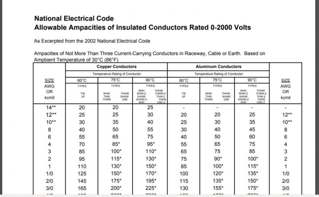
30A/125V shore power cords are typically constructed of AWG 10 conductors which have an ampacity of 60A @ 30C and 51A @ 50C. The ABYC considers shore power cables as operating in a 30C environment. A normal shore power cable has the ampacity to handle up to 60A.
The weak link for passing 50A from a 50A/250V split phase into a wye would be the shore power inlet and the cable ends of the 30A/125V cable.
sdowney717
Guru
- Joined
- Jan 26, 2016
- Messages
- 2,264
- Location
- United States
- Vessel Name
- Old Glory
- Vessel Make
- 1970 Egg Harbor 37 extended salon model
Post #13
30A/125V shore power cords are typically constructed of AWG 10 conductors which have an ampacity of 60A @ 30C and 51A @ 50C. The ABYC considers shore power cables as operating in a 30C environment. A normal shore power cable has the ampacity to handle up to 60A.
The weak link for passing 50A from a 50A/250V split phase into a wye would be the shore power inlet and the cable ends of the 30A/125V cable.
Really, a !0 gauge wire carrying 60 amps at 30*C?
I have not heard this before.
Ampacity charts say otherwise.
http://www.usawire-cable.com/pdfs/nec ampacities.pdf
On my twin 30 amp setup, for the wire between inlets to 30 amp breakers, to panel, I used 8 gauge wires. At the time, I though why not use two 40 amp breakers since 8 gauge wire can handle that, but what stopped me was the shore cable size of 10 gauge, being 10 gauge is limited to 30 amps.
Regardless not had any troubles with what I have. I draw 12 to 13 amps for the cruisair heat pump, and about same for MW oven, and the oven wont run that long. Our marina power, the volts drop to about 100 vac, if I draw 30 amps through my single shore power, which is not very good. I also don't bother with hooking up the other shore cable to the plug next to it. I could but so far I don't regularly use that much power. I used a DPDT 30 amp switch (wired with 8 gauge wires) and joined 2 shoreline into one to power the whole boat AC system through one cable, because some marina's only give you one power outlet. And some marinas are only 1 15 amp outlet too.. When I do the one shore cable to run whole boat, I turn off the shore power inlet breaker to the other wire so as to not energize the prongs on that inlet. And that twin 30 amp breaker box has a lock on it so someone can't just lift the lid and turn it on accidently. There is probably a better way to automate this without moving switches. Might have been easier making my own shore splitter, but that would have been more expensive. I only had to buy one switch to do what I have now.
I have been to too many places where your offered only a single outlet for power, and no fun powering up only half the boat.
Last edited:
psneeld
Guru
The ampacity charts I have seen show 105 degree rated insulation amoacity at 60 A.
Below and others...for ampacity, not the recommended for normal loading.
https://www.westmarine.com/WestAdvi...MIs6708qzT3AIVmoTICh06OweOEAAYASAAEgJwxPD_BwE
Below and others...for ampacity, not the recommended for normal loading.
https://www.westmarine.com/WestAdvi...MIs6708qzT3AIVmoTICh06OweOEAAYASAAEgJwxPD_BwE
Last edited:
sdowney717
Guru
- Joined
- Jan 26, 2016
- Messages
- 2,264
- Location
- United States
- Vessel Name
- Old Glory
- Vessel Make
- 1970 Egg Harbor 37 extended salon model
The ampacity charts I have seen show 105 degree rated insulation amoacity at 60 A.
Below and others...for ampacity, not the recommended for normal loading.
https://www.westmarine.com/WestAdvi...MIs6708qzT3AIVmoTICh06OweOEAAYASAAEgJwxPD_BwE
Got a link?
Here a quick search turned up this and agrees with everything else I have ever seen.
30 amps at 60*c
40 amps maximum at 90*c for better grade of insulation
http://www.usawire-cable.com/pdfs/nec ampacities.pdf
Attachments
sdowney717
Guru
- Joined
- Jan 26, 2016
- Messages
- 2,264
- Location
- United States
- Vessel Name
- Old Glory
- Vessel Make
- 1970 Egg Harbor 37 extended salon model
The ampacity charts I have seen show 105 degree rated insulation amoacity at 60 A.
Below and others...for ampacity, not the recommended for normal loading.
https://www.westmarine.com/WestAdvi...MIs6708qzT3AIVmoTICh06OweOEAAYASAAEgJwxPD_BwE
That WM link is for 12vdc runs of only 10 to 15 foot length with a 10% voltage drop!
Who uses such a short shore power cord? And we are talking of AC power.
Use 10% voltage drop for non-critical applications such as windlass, cabin lights, circuits other than running lights, electronics or panel board feeds. Remember that the Length is a "round trip" distance. This table is for 12-Volt systems only.
sdowney717
Guru
- Joined
- Jan 26, 2016
- Messages
- 2,264
- Location
- United States
- Vessel Name
- Old Glory
- Vessel Make
- 1970 Egg Harbor 37 extended salon model
Total wattage must mean something here, low voltage of 12vdc can carry a few more amps because the total wattage is much less than for higher voltage AC wire of more amps.
60 amps DC times 12 vdc = 720 watts
60 amps AC times 125 vac = 7500 watts
So about 10 times the wattage for the same amps, wattage is power.
.
AC line carries a lot more power so the gauge needs to be bigger wire for similar amp usage.
The NEC wont let you get away with it, using a 10 gauge wire to carry 60 amps of power.. No code inspector would authorize that either.
Wires get hot, voltage will drop a lot, insulation will melt, the wires will arc and short and might catch something on fire.
A breaker may not trip, not all shorts have low resistance enough to pass sufficient current to trip a breaker. The wires can also just got real hot, even smoking smouldering burning hot.
Last edited:
psneeld
Guru
Attachments
sdowney717
Guru
- Joined
- Jan 26, 2016
- Messages
- 2,264
- Location
- United States
- Vessel Name
- Old Glory
- Vessel Make
- 1970 Egg Harbor 37 extended salon model
Shore power cable is heavily sheathed!
So will not be dissipating as much heat.
And it is not made from Anchor wire rated to 105*c, the insulation on anchor wire allows for the higher ampacity.
We are talking about yellow shore power cables right?
I can melt that insulation using my soldering gun. I have seen high performance high heat wires, and the wire insulation is very different. Some is silicone based and it does not melt.
I am happy to have used 8 gauge wires inside my boat to the panel. That ups my safety factor a lot. My weakest link is the thick heavy shore cable, just plain old Marinco, and I always knew that and it is the only failure I have ever had. One of my yellow shore cables got a pinhole down to the wire, likely got pinched between boat and dock or something and was shorting in the water. Ate up 6 feet of copper inside the cable itself. Happened during a storm of some kind. Salt water, sizzling away, consuming itself, no power at the boat for days.
Anyhow, ok just be stubborn.
Last edited:
TomandJeri
Senior Member
Shore power cable is heavily sheathed!
So will not be dissipating as much heat.
And it is not made from Anchor wire rated to 105*c, the insulation on anchor wire allows for the higher ampacity.
We are talking about yellow shore power cables right?
To that point, something to keep in mind is that shore power cordsets are UL and CSA (Marinco, at least) listed assemblies, not individual or bundled insulated conductors in free air (like a cable tray). That includes sheathing, plugs, receptacles, and the conductors inside, which may or may not have 105C insulation, and the plugs/receptacles at either end are 30A or 50A rated (and listed) anyway.
I don't know how the ABYC addresses this, but the NEC at least will only allow conductor ampacity higher than the 60C value if the terminations also are rated 75 or 90C (most only go to 75C), and even then, small conductors are limited to the familiar 15/20/30A values regardless of the Table 310.16 values for most common circuits (other than motor, hermetic A/C, welder, and some other 'special' circuits).
But I would use caution in selecting conductors for continuous loads in a boat, in large part because I'm not familiar enough with the codes and standards for marine wiring. Which means I shouldn't be selecting conductors or doing wiring on a boat in the first place, I suppose.

Posts #17, 18, and 19
And, again, how is your comment germane to the discussion of deriving two legs of 30A/125V shore power from a shore power pedestal with an 50A/250V outlet (split phase).
My post was simply pointing out that the conductors that make up the 30A/125V shore power cables are really not the weak links in this system. Rather particular attention has to be paid to the shore power inlet on the vessel and the cable ends.
Not really and certainly not germane to the discussion of shore power cable ampacity.Total wattage must mean something here
Just to be clear: amps is the unit of measure for current flow; watts is the unit of measure for power.The NEC wont let you get away with it, using a 10 gauge wire to carry 60 amps of power.
By definition, a short circuit is "an electrical circuit of lower resistance than that of a normal circuit, typically resulting from the unintended contact of components and consequent accidental diversion of the current.not all shorts have low resistance enough to pass sufficient current to trip a breaker.
And, again, how is your comment germane to the discussion of deriving two legs of 30A/125V shore power from a shore power pedestal with an 50A/250V outlet (split phase).
My post was simply pointing out that the conductors that make up the 30A/125V shore power cables are really not the weak links in this system. Rather particular attention has to be paid to the shore power inlet on the vessel and the cable ends.
sdowney717
Guru
- Joined
- Jan 26, 2016
- Messages
- 2,264
- Location
- United States
- Vessel Name
- Old Glory
- Vessel Make
- 1970 Egg Harbor 37 extended salon model
To that point, something to keep in mind is that shore power cordsets are UL and CSA (Marinco, at least) listed assemblies, not individual or bundled insulated conductors in free air (like a cable tray). That includes sheathing, plugs, receptacles, and the conductors inside, which may or may not have 105C insulation, and the plugs/receptacles at either end are 30A or 50A rated (and listed) anyway.
I don't know how the ABYC addresses this, but the NEC at least will only allow conductor ampacity higher than the 60C value if the terminations also are rated 75 or 90C (most only go to 75C), and even then, small conductors are limited to the familiar 15/20/30A values regardless of the Table 310.16 values for most common circuits (other than motor, hermetic A/C, welder, and some other 'special' circuits).
But I would use caution in selecting conductors for continuous loads in a boat, in large part because I'm not familiar enough with the codes and standards for marine wiring. Which means I shouldn't be selecting conductors or doing wiring on a boat in the first place, I suppose.
My 'guess', is a yellow 30 amp shore cord is rated only for 30 amps, not to be used for 50 or 60 amps. I have cut them apart and replaced ends, and it is just a 10 gauge wire in there, insulation is nothing special. The longer it runs overspec at high amps, the hotter and more dangerous the situation gets.
sdowney717
Guru
- Joined
- Jan 26, 2016
- Messages
- 2,264
- Location
- United States
- Vessel Name
- Old Glory
- Vessel Make
- 1970 Egg Harbor 37 extended salon model
Post #13
30A/125V shore power cords are typically constructed of AWG 10 conductors which have an ampacity of 60A @ 30C and 51A @ 50C. The ABYC considers shore power cables as operating in a 30C environment. A normal shore power cable has the ampacity to handle up to 60A.
The weak link for passing 50A from a 50A/250V split phase into a wye would be the shore power inlet and the cable ends of the 30A/125V cable.
Again, I totally disagree with this, your saying a 30 amp shore cord can handle 60 amps. That is irresponsible thing to say, IMO.
Do you have evidence to say they can be used for 60 amps?
STW wire, 10 gauge is rated for 30 amps.
https://www.centurywire.com/home/portable-power-cords/stw-portable-power-cords-600v/
https://www.southwire.com/ProductCatalog/XTEInterfaceServlet?contentKey=prodcatsheet307
Last edited:
twistedtree
Guru
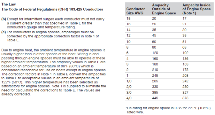
I've never read the CG regs on ampacity as referenced in the CFRs, and quite surprised to see them as high as they are.
Give or take, NEC and ABYC say 30A for #10 wire, where the CFR says 60A.
diver dave
Guru
- Joined
- Jan 13, 2017
- Messages
- 2,570
- Location
- United States
- Vessel Name
- Coquina
- Vessel Make
- Lagoon 380
Again, I totally disagree with this, your saying a 30 amp shore cord can handle 60 amps. That is irresponsible thing to say, IMO.
Do you have evidence to say they can be used for 60 amps?
STW wire, 10 gauge is rated for 30 amps.
https://www.centurywire.com/home/portable-power-cords/stw-portable-power-cords-600v/
https://www.southwire.com/ProductCatalog/XTEInterfaceServlet?contentKey=prodcatsheet307
Charlie is correct. The CABLE is rated at 105 deg, therefore the high current rating. Of course, the SYSTEM is only good for 30A, due in large part to the connectors at each end.
FEP insulated 10AWG is rated at 75Amps, btw.
psneeld
Guru
I've never read the CG regs on ampacity as referenced in the CFRs, and quite surprised to see them as high as they are.
Give or take, NEC and ABYC say 30A for #10 wire, where the CFR says 60A.
I think you are quoting allowable based on certain factors versus pure ampacity of #10 which can be higher.
Sorta like cars can safely go faster than the speed limit, but different places have different speed limits. The car may be limited also by tires (likened to the insulation rating).
So allowed ampacity can be anything some organization allows, but the actual wire with the right insulation and operating conditions could safely handle double that allowed ampacity.
Last edited:
twistedtree
Guru
Charlie is correct. The CABLE is rated at 105 deg, therefore the high current rating. Of course, the SYSTEM is only good for 30A, due in large part to the connectors at each end.
FEP insulated 10AWG is rated at 75Amps, btw.
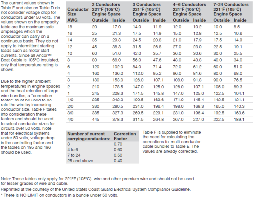
This has been quite interesting. I have always just gone based on the NEC limits, but looking at the ABYC std, the max allowed current does depend on the insulation temp rating, and whether the conductors are individual or if they are bundled into a cable. Attached are the tables for different cable configs & insulation temp ratings.
Table VI-B is applicable for the #10, 30A shore cord under discussion. Current ratings range from 28A for 60C insulation, to 42A for 105C insulation.
The only place I see 60A allowed is in Table VI-A for individual, un-bundled conductors with 105C insulation.
Attachments
Similar threads
- Replies
- 9
- Views
- 641
- Replies
- 16
- Views
- 915
- Replies
- 6
- Views
- 233
- Replies
- 0
- Views
- 232
- Replies
- 22
- Views
- 2K