Without hijacking the thread too much, I had two 6v batteries in each main engine start bank and I was told by a very experienced ABYC marine electrician to replace them with one 12VDC 8D and not to use 2 x 6VDc. One set had failed anyway so no great loss. Has anyone heard this from other sources? It was news to me.
You are using an out of date browser. It may not display this or other websites correctly.
You should upgrade or use an alternative browser.
You should upgrade or use an alternative browser.
House & Start Bank Design Issue
- Thread starter Wil
- Start date
The friendliest place on the web for anyone who enjoys boating.
If you have answers, please help by responding to the unanswered posts.
If you have answers, please help by responding to the unanswered posts.

")
menzies
Guru
Not sure if this has been mentioned in all of this, I couldn't see it. I would also make sure that you have "pull" or "punch" breakers for both your thruster and windlass, and they are in easily accessed locations. And make sure your crew know where they are and how to activate them.
FF
Guru
- Joined
- Oct 12, 2007
- Messages
- 22,552
"ABYC marine electrician to replace them with one 12VDC 8D and not to use 2 x 6VDc."
The most common change for an 8D 12v start system is (2) group 31 12v start batts , A heck of a lot easier to get in place.
Multiple 6v deep cycle batts are a great way to construct a house batt system
The most common change for an 8D 12v start system is (2) group 31 12v start batts , A heck of a lot easier to get in place.
Multiple 6v deep cycle batts are a great way to construct a house batt system
Not bashing KKY in any way, but they do not purport to have been ABYC compliant on vessels of this vintage (2003). KKY does not participate in the NMMA/ABYC Compliance Program, and I can attest they, like many other builders, are not 100% ABYC compliant even today. Thus, I would not assume the vessel's electrical system was ABYC compliant when built 17-18 years ago, nor would I assume the schematics from that era are necessarily ABYC compliant, they may be but it's not guaranteed. Again, not bashing them, they make a fine vessel, it just is not accurate to say the design would have been scrutinized for ABYC compliance.
And, the ABYC certifications are not chapter specific, a tech simply needs to have an ABYC Electrical certification. There is no such thing as an E-10 or A-31 certification.
As far as battery banks under V berths are concerned, I realize it's a fact of life but I don't like it. Make sure the compartment is vented at its apex. As you note, batteries must be very secure, they do not need to be in boxes and I would not recommend it, trays with brackets would be ideal. Make certain you have a readily master disconnect switch between battery and thruster.
Riverguy
Senior Member
- Joined
- Feb 17, 2013
- Messages
- 285
- Location
- USA
- Vessel Name
- Serendipitous
- Vessel Make
- Mainship 390, Bayliner 3258, Bayliner 4788
...voltage drop is not related to I^2, rather just I. Power dissipation in the wire is usually not a problem.
Hi DDW,
I think you misunderstood my point -- I'll take the blame for that.
It's true that voltage = current x resistance, so voltage drop is proportional to resistance and current...but voltage drop is not the problem here. The problem is power loss in the wiring.
Power = [current^2] x Resistance (aka I-Squared-R)
The power dissipated in any circuit is equal to the current squared times the resistance. Hopefully there is no argument here. This is true for a simple resistor, and it is true for a wire as well. Therefore, wiring size is dictated by I-squared-R (which is why power losses in wiring are called "I2R" losses).
You don't need a BSEE to prove this to yourself. Download any wire sizing table from anywhere you like (ABYC, etc.) Next, size the wiring for any load you like, in watts (recalling that watts = current x voltage). Finally, look up the wire size on the table.
The Blue Sea Systems Circuit Wizard app (for Android or iOS) makes this really easy.
Circuit Wizard - Blue Sea Systems
You will find that (for example):
1) 4,800 watts @ 24V = 200A, and this requires AWG #2.
2) 4,800 watts @ 12V = 400A, but this requires AWG 0000.
That's a savings of five AWG sizes difference for the same 4,800 watts... just by doubling the voltage!
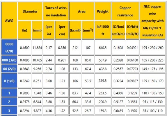
If you're really interested, check the AWG standards tables and you'll see that the weight of the copper in AWG 0000 is more than four times the weight of the copper in AWG 2.
Worldwide...the trend overall is toward higher voltages, because this means less copper is needed. When you double the voltage, you reduce the copper needed by 75%. Yes...this is eco-friendly.
Just for fun, carry this forward to 240V, you will see you only need 20A to deliver 4800 watts...and now you only need AWG 16 wire to supply a 4800 watt load.
Now...in case you ever wondered why almost every country in the world (except the U.S.) uses 220-240v instead of 120v...it's because it needs only 25% as much copper to deliver the same watts.
For you techno-historians out there, it's Edison vs. Westinghouse all over again....
Edison vs. Westinghouse: A Shocking Rivalry
Are we having fun yet?
OP
OP
Wil
Senior Member
- Joined
- Jul 8, 2013
- Messages
- 187
- Location
- US
- Vessel Name
- Gone Walkabout
- Vessel Make
- 1999 KadeyKrogen 39
Good story about Edison, Tesla, and Westinghouse.
Looking at the I^2R loss issue from the other end; my existing 12v windlass is a bit puny, a 24v windlass would be much more powerful. I need to figure out just how powerful (watts) a 24v windlass I can go with using the existing cable gauge and pos/neg total run from engine room to forepeak. Head scratching time again....fun indeed.
Looking at the I^2R loss issue from the other end; my existing 12v windlass is a bit puny, a 24v windlass would be much more powerful. I need to figure out just how powerful (watts) a 24v windlass I can go with using the existing cable gauge and pos/neg total run from engine room to forepeak. Head scratching time again....fun indeed.
Worldwide...the trend overall is toward higher voltages, because this means less copper is needed. When you double the voltage, you reduce the copper needed by 75%. Yes...this is eco-friendly.
Just for fun, carry this forward to 240V, you will see you only need 20A to deliver 4800 watts...and now you only need AWG 16 wire to supply a 4800 watt load.
Now...in case you ever wondered why almost every country in the world (except the U.S.) uses 220-240v instead of 120v...it's because it needs only 25% as much copper to deliver the same watts.
For you techno-historians out there, it's Edison vs. Westinghouse all over again....
https://www.smithsonianmag.com/history/edison-vs-westinghouse-a-shocking-rivalry-102146036/
Are we having fun yet?
OP
OP
Wil
Senior Member
- Joined
- Jul 8, 2013
- Messages
- 187
- Location
- US
- Vessel Name
- Gone Walkabout
- Vessel Make
- 1999 KadeyKrogen 39
I decided to stay with the system as it is--Machinery (Start) Bank in engine room operates the windlass and thruster, as well starts the main engine and generator. No batteries under the bed for now. A 500A/0000 paralleling circuit from the FF 900Ah House Bank to the FF 220Ah Machinery Bank will be an emergency backup. Lot less work involved too.
Feel better about this series-parallel system now that I understand it more. It doesn't have the spark potential I thought it had, plus it will be much easier to feed a charge to it from the House Bank, which in turn is charged by a 200A continuous alternator.
Feel better about this series-parallel system now that I understand it more. It doesn't have the spark potential I thought it had, plus it will be much easier to feed a charge to it from the House Bank, which in turn is charged by a 200A continuous alternator.
As far as battery banks under V berths are concerned, I realize it's a fact of life but I don't like it. Make sure the compartment is vented at its apex. As you note, batteries must be very secure, they do not need to be in boxes and I would not recommend it, trays with brackets would be ideal. Make certain you have a readily master disconnect switch between battery and thruster.
Riverguy
Senior Member
- Joined
- Feb 17, 2013
- Messages
- 285
- Location
- USA
- Vessel Name
- Serendipitous
- Vessel Make
- Mainship 390, Bayliner 3258, Bayliner 4788
Maybe you should measure the voltage at your thruster when it's running. As voltage drops on a DC motor, RPM decreases, the thruster heats up faster, and duty cycle shortens. On my boat, the cable runs to the thruster were probably 25 to 30' (total length 50 to 60'). Significant voltage drop. Now, the total cable length (out and back) is about 7'.
Ted
You're absolutely right about insufficient voltage and it's effect on motor windings -- in fact I recently replaced a 12v vetus thruster motor for that very reason, but it had to do with the original installer's poor cable terminations and an undersized battery switch, not cable lengths.
For a 24v thruster, the dominant factor in the size of the wiring chosen will be ampacity, not voltage drop, even for longer runs. Because of this, voltage drop is not usually a problem in 24v thruster wiring.
Another way of saying this; if the thruster wiring is sized correctly for ampacity, it will generally be oversized from a voltage-drop standpoint. At 24v, this will be true up to about 100 feet IIRC.
Every wire needs to be sized for both ampacity and voltage drop, and the two will almost always be different. Sizing for ampacity is independent of length and has to do with how much heat can be allowed to dissipate from the wire -- this is why wire with higher insulation temps can carry more current, even though the copper might be identical.
Whether you use ABYC tables, or actually do the math, you will find that a 24v, 200A circuit that is sized correctly for ampacity will wind up being oversized for voltage drop as long as the total wire length is under about 100 feet.
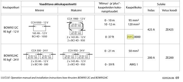
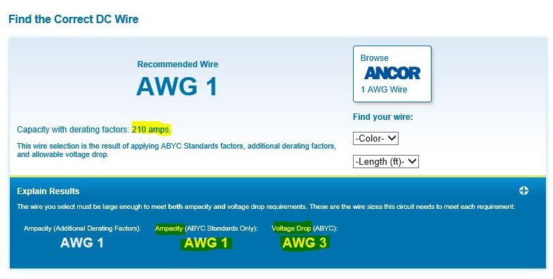
Looking at the attached table from Vetus, they want AWG1 for 24v and this is regardless of length (up to 60'), again because ampacity is the dominant factor. Running the Vetus engineering numbers against the ABYC sizing tables, you'll see that you need AWG1 for ampacity but only need AWG3 for voltage drop --- even at 60 feet.
Not saying that voltage drop isn't ever a problem, but it should not be if wiring is sized correctly. If you have a voltage drop problem in a 24v thruster circuit, it will most likely be due to undersized wiring or bad terminations.
Attachments
Riverguy
Senior Member
- Joined
- Feb 17, 2013
- Messages
- 285
- Location
- USA
- Vessel Name
- Serendipitous
- Vessel Make
- Mainship 390, Bayliner 3258, Bayliner 4788
I-squared-R
Re: "25% of the copper will dissipate the same power in a 24V system,"
Only if we are also trying to double the total watts in the circuit at the same time. That's not the case here.
We have to start with watts, and work our way back.
Bottom line, any time we double the voltage, we can use 75% less copper, because I^2R.
In case you ever wondered why the 'high-tension' lines that distribute electricity in the grid over many hundreds of miles run in the range of 150,000 to 750,000 volts...at surprisingly low current...it's because I^2R.
https://www.engineersedge.com/copper_wire.htm
Not true. 25% of the copper will dissipate the same power in a 24V system, but voltage drop is not related to I^2, rather just I. Power dissipation in the wire is usually not a problem.
Re: "25% of the copper will dissipate the same power in a 24V system,"
Only if we are also trying to double the total watts in the circuit at the same time. That's not the case here.
We have to start with watts, and work our way back.
- If we have a circuit that needs to supply a given power (in watts), doubling the voltage will halve the current.
- Halving the current means we can use a (much) smaller wire.
- The reason we can use (much) smaller wire is I^2R.
Bottom line, any time we double the voltage, we can use 75% less copper, because I^2R.
In case you ever wondered why the 'high-tension' lines that distribute electricity in the grid over many hundreds of miles run in the range of 150,000 to 750,000 volts...at surprisingly low current...it's because I^2R.
https://www.engineersedge.com/copper_wire.htm
Attachments

Last edited:
Wil,
The simple solution to this is the 12V to 24V Sterling Power Pro Batt Ultra Battery to Battery charger (B2B) model BB122470.
The Sterling 12V to 24V B2B's were was specifically designed for this type of use. It is a fully custom programmable, multi-stage DC to DC charger, has a target battery temp sensor as standard equipment, a volt sense circuit and can be either ignition excited or voltage triggered. There is also a remote display available too.
Unlike ACR's, Echo Chargers, Digital Duo Chargers etc. this unit can float the bow bank even if house is still bulk charging as it is a true, fully independent, battery charger not just a voltage follower.
JDCAVE
Guru
- Joined
- Apr 3, 2011
- Messages
- 2,908
- Location
- Canada
- Vessel Name
- Phoenix Hunter
- Vessel Make
- Kadey Krogen 42 (1985)
...For a 24v thruster, the dominant factor in the size of the wiring chosen will be ampacity, not voltage drop, even for longer runs. Because of this, voltage drop is not usually a problem in 24v thruster wiring.
But I suspect that voltage drop has less to do with wire size and much more to do with what the batteries and alternators can deliver during use of the thruster. What voltage, as measured at the batteries, is acceptable during operation? As a battery nears end of life they may not deliver an acceptable voltage. The appropriate question is, when is end of life?
In my situation, the existing batteries for my Wesmar 24VDC bow thruster (unknown hp) are Northstar NSB M12-210, which are combined . They are a very expensive AGM, and are basically a 4D at 132 lbs a piece. The maintenance logbook indicates they were installed February 2010, so they have 9 seasons. Realistically they are nearing end of life. So I did some tests:
With the charger just turned off for the test. Batteries are at 13.27 Volts, measured at the battery with digital meter.
5 second thruster test: drops down to 9.2 volts during the test. After the test, recovers to 12.94 volts quite quickly. I did this 4-5 times.
The thruster seems ok, perhaps a little less jump than I remember. Is the voltage drop to 9 volts excessively low?
In another test, I used the clamp meter and measured a peak draw of 368 amps @ 24 VDC = 8832 watts / 745 = 11.8 electrical hp.
However I had measured 9.3 VDC at the batteries during operation, which would suggest a possible correction of:
2*9.3/24*11.8= 9.2 effective hp.
Does this make sense?
Jim
Riverguy
Senior Member
- Joined
- Feb 17, 2013
- Messages
- 285
- Location
- USA
- Vessel Name
- Serendipitous
- Vessel Make
- Mainship 390, Bayliner 3258, Bayliner 4788
But I suspect that voltage drop has less to do with wire size and much more to do with what the batteries and alternators can deliver during use of the thruster... 5 second thruster test: drops down to 9.2 volts during the test. After the test, recovers to 12.94 volts quite quickly. I did this 4-5 times....Does this make sense?
Jim
You're talking about a different kind of 'voltage drop'.
When engineers talk about voltage drop, they are referring to the difference between the voltage at the current source compared to the voltage at the load point. All wires have resistance, and so a wire will 'drop' the voltage by dissipating heat along it's length when under load.
Excessive voltage drop in a wire happens when too small of a wire feeds too big of a load over too long a distance.
JDCAVE
Guru
- Joined
- Apr 3, 2011
- Messages
- 2,908
- Location
- Canada
- Vessel Name
- Phoenix Hunter
- Vessel Make
- Kadey Krogen 42 (1985)
House & Start Bank Design Issue
Yes, I’m aware of that. I’ve got 2/0 cables with very short runs to the thruster. 4/0 is possible I suppose, but my point is when you engage the thruster there is a large voltage drop that has very little to do with undersized wires, at least in my situation. There are other factors at play. So the question remains: how large a drop is too large?
Yes, I’m aware of that. I’ve got 2/0 cables with very short runs to the thruster. 4/0 is possible I suppose, but my point is when you engage the thruster there is a large voltage drop that has very little to do with undersized wires, at least in my situation. There are other factors at play. So the question remains: how large a drop is too large?
Yes, I’m aware of that. I’ve got 2/0 cables with very short runs to the thruster. 4/0 is possible I suppose, but my point is when you engage the thruster there is a large voltage drop that has very little to do with undersized wires, at least in my situation. There are other factors at play. So the question remains: how large a drop is too large?
What you are referring to is what is often referred to as battery voltage sag. If you check it with a fast volt meter, Fluke 289 etc., you may even see it hit 7V or lower then begin to rebound. As batteries age their ability to survive a massive in-rush current and hold voltage will drop off. When you stack batter voltage sag on top of wire and termination drop is where we start to get into rather anemic bow thruster performance. The TPPL AGM's do about the best at handling the in-rush, for lead acid batteries, but the are not immune from a voltage sag under a high load.
JDCAVE
Guru
- Joined
- Apr 3, 2011
- Messages
- 2,908
- Location
- Canada
- Vessel Name
- Phoenix Hunter
- Vessel Make
- Kadey Krogen 42 (1985)
House & Start Bank Design Issue
Thanks CMS. I’ve got these Northstar NSB M12-210’s. They are expensive puppies, but supply 2350 MCA’s. As they are so expensive, would a Group 32 suffice, or do I need to replace with something similar to the M12-210’s?
I would like to get them tested, but don’t have a meter myself and I think I would need a high end model* to test for cranking amps for such a high potential output.
*Edit: something like a Midtronics.
Jim
Last edited:
OP
OP
Wil
Senior Member
- Joined
- Jul 8, 2013
- Messages
- 187
- Location
- US
- Vessel Name
- Gone Walkabout
- Vessel Make
- 1999 KadeyKrogen 39
CMS,
Thanks for the recommendation. I'm aware of the Sterling chargers, have a 40 amp one now. For now I'm sticking with the existing series-parallel Start bank charging system, now that I know it doesn't feed back to the 12v House bank when operating in 24v mode.
Thanks for the recommendation. I'm aware of the Sterling chargers, have a 40 amp one now. For now I'm sticking with the existing series-parallel Start bank charging system, now that I know it doesn't feed back to the 12v House bank when operating in 24v mode.
Wil,
The simple solution to this is the 12V to 24V Sterling Power Pro Batt Ultra Battery to Battery charger (B2B) model BB122470.
The Sterling 12V to 24V B2B's were was specifically designed for this type of use. It is a fully custom programmable, multi-stage DC to DC charger, has a target battery temp sensor as standard equipment, a volt sense circuit and can be either ignition excited or voltage triggered. There is also a remote display available too.
Unlike ACR's, Echo Chargers, Digital Duo Chargers etc. this unit can float the bow bank even if house is still bulk charging as it is a true, fully independent, battery charger not just a voltage follower.
Hi DDW,
I think you misunderstood my point -- I'll take the blame for that.
It's true that voltage = current x resistance, so voltage drop is proportional to resistance and current...but voltage drop is not the problem here. The problem is power loss in the wiring.
Power = [current^2] x Resistance (aka I-Squared-R)
Actually I am a BSEE and very familiar with these formulas. You missed my point - power loss on the charging or thruster wiring of a boat is for practical purposes a don't care. It is voltage loss that is hard on the motors. Power loss in long distance power distribution may be of concern to your local power company, but not on your boat except for some very unusual circumstances.
Doubling the voltage loss in the wiring will double the power reduction of the thruster as a result. It's pretty rare to find an owner who says, "I'd sure like it if my thrusters were less effective."
Riverguy
Senior Member
- Joined
- Feb 17, 2013
- Messages
- 285
- Location
- USA
- Vessel Name
- Serendipitous
- Vessel Make
- Mainship 390, Bayliner 3258, Bayliner 4788
Much too large...change 'em...quick!
Re: "So the question remains: how large a drop is too large?"
Sorry JD, I misinterpreted the question. As previously mentioned, voltage drop is a function of resistance in a circuit somewhere. Voltage 'sag' under load is a measure of the health of your battery.
Now...short answer...given the size (CCA) of your battery bank and the current draw of your thruster, the voltage sag you are seeing is way, WAY too much. You are definitely in the 'danger zone'.
At 9.2v under your test load...these batteries are long gone given that (a) you put a 368 amp load on a battery bank of 2,350 MCA (about 1700 CCA), so your test load was only 22% of CCA, and (b) your test load was only five seconds...then you should have been way, way above 9.2v.
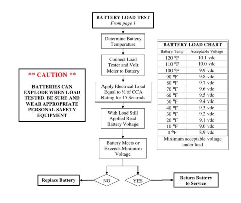
At 50% of CCA (roughly 850 amps) for 15 seconds, these batteries should have been at 9.7v @ 80 degrees.
Of course, we don't test big batteries that way anymore, but your informal test readings are so low that these batteries are now a safety hazard. After nine years, time to get them off of your boat.
I recommend you don't conduct any further load testing -- this is when batteries explode. For that matter, you probably don't want to use that thruster unless you absolutely have to...
...my point is when you engage the thruster there is a large voltage drop that has very little to do with undersized wires, at least in my situation. There are other factors at play. So the question remains: how large a drop is too large?
Re: "So the question remains: how large a drop is too large?"
Sorry JD, I misinterpreted the question. As previously mentioned, voltage drop is a function of resistance in a circuit somewhere. Voltage 'sag' under load is a measure of the health of your battery.
Now...short answer...given the size (CCA) of your battery bank and the current draw of your thruster, the voltage sag you are seeing is way, WAY too much. You are definitely in the 'danger zone'.
At 9.2v under your test load...these batteries are long gone given that (a) you put a 368 amp load on a battery bank of 2,350 MCA (about 1700 CCA), so your test load was only 22% of CCA, and (b) your test load was only five seconds...then you should have been way, way above 9.2v.
At 50% of CCA (roughly 850 amps) for 15 seconds, these batteries should have been at 9.7v @ 80 degrees.
Of course, we don't test big batteries that way anymore, but your informal test readings are so low that these batteries are now a safety hazard. After nine years, time to get them off of your boat.
I recommend you don't conduct any further load testing -- this is when batteries explode. For that matter, you probably don't want to use that thruster unless you absolutely have to...
Attachments
JDCAVE
Guru
- Joined
- Apr 3, 2011
- Messages
- 2,908
- Location
- Canada
- Vessel Name
- Phoenix Hunter
- Vessel Make
- Kadey Krogen 42 (1985)
Thanks Riverguy. It is my belief that those measurements I provided were accurate. The Clamp meter is a “Blueseas” meter and while not a Fluke, it is a reputable meter for weekend warrior use.
Note that these tests were done during a 2 day period, In the middle of January, the batteries would have been at about 40 degrees F or less as the boat has minimal heat that time of year.
Jim
Note that these tests were done during a 2 day period, In the middle of January, the batteries would have been at about 40 degrees F or less as the boat has minimal heat that time of year.
Jim
JDCAVE
Guru
- Joined
- Apr 3, 2011
- Messages
- 2,908
- Location
- Canada
- Vessel Name
- Phoenix Hunter
- Vessel Make
- Kadey Krogen 42 (1985)
Thanks Riverguy. It is my belief that those measurements I provided were accurate. The Clamp meter is a “Blueseas” meter and while not a Fluke, it is a reputable meter for weekend warrior use.
Note that these tests were done during a 2 day period, In the middle of January, the batteries would have been at about 40 degrees F or less as the boat has minimal heat that time of year.
Damn but these are expensive batteries! Can I get by with something with less MCA? As they are under the master berth, I need AGM.
Jim
Yes, I’m aware of that. I’ve got 2/0 cables with very short runs to the thruster. 4/0 is possible I suppose, but my point is when you engage the thruster there is a large voltage drop that has very little to do with undersized wires, at least in my situation. There are other factors at play. So the question remains: how large a drop is too large?
When you did your battery measurements, the open circuit voltage should be measured after all charging sources have been removed for at least 4 hours so I suspect that your initial OCV is a little high. While SOH cannot be determined by SOC . According to your tests after 5 runs of 5 seconds drawing 360 amps the batteries OCV was 12.94 which Northstar considers fully charged. Did you happen to measure OCV on both batteries prior to and after running the thrusters? they should be within a few percent of each other. The batts are getting long in tooth but Northstar rates them for about 5000 cycles at a 20% discharge rate. I would monitor the voltage and temperature after running the thruster for awhile and only replace them if there are concerns with OCV collapsing or temp.
From Northstar manual
The SOC of a fully recharged battery is 100%. An estimate of the SOC can be obtained by measuring the Open Circuit Voltage (OCV) of the battery. The OCV of a battery is the voltage measured between its positive and negative terminals without the battery connected to an external circuit (load). It is very important to take OCV reading at least 3 hours after a charge period, or at least 10 min after a discharge event. Measurements will be inaccurate if these rest times are too short. A good quality voltmeter is all that is required to measure the OCV.
Sorry couldn't copy the graph:
The graph shows that a healthy, fully charged NSB automotive and marine battery will have an OCV of approximately 13.0 V.
JDCAVE
Guru
- Joined
- Apr 3, 2011
- Messages
- 2,908
- Location
- Canada
- Vessel Name
- Phoenix Hunter
- Vessel Make
- Kadey Krogen 42 (1985)
When you did your battery measurements, the open circuit voltage should be measured after all charging sources have been removed for at least 4 hours so I suspect that your initial OCV is a little high. While SOH cannot be determined by SOC . According to your tests after 5 runs of 5 seconds drawing 360 amps the batteries OCV was 12.94 which Northstar considers fully charged. Did you happen to measure OCV on both batteries prior to and after running the thrusters? they should be within a few percent of each other. The batts are getting long in tooth but Northstar rates them for about 5000 cycles at a 20% discharge rate. I would monitor the voltage and temperature after running the thruster for awhile and only replace them if there are concerns with OCV collapsing or temp.
From Northstar manual
The SOC of a fully recharged battery is 100%. An estimate of the SOC can be obtained by measuring the Open Circuit Voltage (OCV) of the battery. The OCV of a battery is the voltage measured between its positive and negative terminals without the battery connected to an external circuit (load). It is very important to take OCV reading at least 3 hours after a charge period, or at least 10 min after a discharge event. Measurements will be inaccurate if these rest times are too short. A good quality voltmeter is all that is required to measure the OCV.
Sorry couldn't copy the graph:
The graph shows that a healthy, fully charged NSB automotive and marine battery will have an OCV of approximately 13.0 V.
Thanks for that. I turned the thruster charger off sometime yesterday afternoon and at 13:30 today, it reads 13.06 volts, according to the Victron monitor. The batteries are hard to get at under the berth, so this was measured via the Victron monitor.
Jim
Riverguy
Senior Member
- Joined
- Feb 17, 2013
- Messages
- 285
- Location
- USA
- Vessel Name
- Serendipitous
- Vessel Make
- Mainship 390, Bayliner 3258, Bayliner 4788
Thanks Riverguy.
...tests were done during a 2 day period, In the middle of January, the batteries would have been at about 40 degrees F or less...
...Damn but these are expensive batteries! Can I get by with something with less MCA?...
Jim
Re: "Can I get by with something with less MCA?"
I suspect the answer is yes...but first thing I would do is consult your thruster manual. It will have a minimum recommendation for the total CCA and Ah of the thruster bank. FYI, the term "MCA" is mostly a marketing device. MCA is merely the CCA number...inflated somewhat by taking the spec at a higher temperature.
Note in the example from Vetus attached, they only require a pair of 55 Ah batteries with 500 CCA for the 95 kgf 24v thruster...
Re: "the batteries would have been at about 40 degrees F or less as the boat has minimal heat that time of year"
Ok, but as your load was still only 20% of the CCA (1,830 according to Northstar spec sheet), 9.2 volts still seems too low for that load, especially as these batteries are designed for low internal resistance.
JDCAVE
Guru
- Joined
- Apr 3, 2011
- Messages
- 2,908
- Location
- Canada
- Vessel Name
- Phoenix Hunter
- Vessel Make
- Kadey Krogen 42 (1985)
Thanks Riverguy. It’s time I guess. These batteries are so expensive, that it would be nice to be certain before replacement.
There are quite a variety of motors that were used in the installations of Wesmar Bow Thrusters is and, in my case, there is no identification plate as to the specs of it, amperage, HP, and so forth.
Jim
There are quite a variety of motors that were used in the installations of Wesmar Bow Thrusters is and, in my case, there is no identification plate as to the specs of it, amperage, HP, and so forth.
Jim
JDCAVE
Guru
- Joined
- Apr 3, 2011
- Messages
- 2,908
- Location
- Canada
- Vessel Name
- Phoenix Hunter
- Vessel Make
- Kadey Krogen 42 (1985)
House & Start Bank Design Issue
Update:
I phoned Wesmar and the tech there said that many people were using the Optima Yellow top. However, I had an opportunity to get 2 Northstar 190 FT Red batteries that had seen only light use and were near new. These are much larger batteries than the Optima and have much greater capacity. They are more similar to the current batteries.
I first did tests with the old batteries: voltages checked at the battery terminals and amperage leaving the batteries. I used 3 second bursts on the thruster (batteries combined in series with a Cole Hersee relay).
Old Northstar MS-210, Top battery: Volts: 9.0 Amps: 350
Old Northstar MS-210, Bottom battery: Volts: 9.9 Amps: 350
Average 3308 Watts.
New Northstar 190FT Red, Top battery: Volts: 11.4 Amps: 425
New Northstar 190FT Red, Bottom battery: Volts: 11.14 Amps: 428
Average 4790 Watts, or 45% more than the older ones.
So as Riverguy emphasized, the older batteries are at end of life. The thruster now has considerably more jump.
Last edited:
FF
Guru
- Joined
- Oct 12, 2007
- Messages
- 22,552
"Is the voltage drop to 9 volts excessively low?"
I would not think so, many starters are 9.5V , and are also heavily loaded.
I would not think so, many starters are 9.5V , and are also heavily loaded.
JDCAVE
Guru
- Joined
- Apr 3, 2011
- Messages
- 2,908
- Location
- Canada
- Vessel Name
- Phoenix Hunter
- Vessel Make
- Kadey Krogen 42 (1985)
House & Start Bank Design Issue
While the “starter” comparison is partly valid, you aren’t powering the boat with the starter. As long as it starts the engine within safe limits then it’s fine.
However the bow thruster is powered entirely from these batteries as in its current configuration, the charging source at 30 amps (Digital Duo Charge) is insufficient to contribute much in its operation. At a minimum, the thruster is operating at 70% of its capability, when the calculated power in Watts of the two sets of batteries are compared. In reality, it may even be less than that as the calculated power doesn’t go entirely to operation of the thruster blades, due to inefficiencies in the thruster motor.
Jim
"Is the voltage drop to 9 volts excessively low?"
I would not think so, many starters are 9.5V , and are also heavily loaded.
While the “starter” comparison is partly valid, you aren’t powering the boat with the starter. As long as it starts the engine within safe limits then it’s fine.
However the bow thruster is powered entirely from these batteries as in its current configuration, the charging source at 30 amps (Digital Duo Charge) is insufficient to contribute much in its operation. At a minimum, the thruster is operating at 70% of its capability, when the calculated power in Watts of the two sets of batteries are compared. In reality, it may even be less than that as the calculated power doesn’t go entirely to operation of the thruster blades, due to inefficiencies in the thruster motor.
Jim
FF
Guru
- Joined
- Oct 12, 2007
- Messages
- 22,552
"you aren’t powering the boat with the starter" not really doing much boat powering with a thruster as many have short on times and longer cooling requirements.
Any time there is a voltage missing problem , I check the ground circuit first.
Then the temperature gun will show up really bad connections.
The final (desperation) move is to check operating voltage at each and every wire connection. Usually start from the batt and work down the line.
" MCA" is mostly a marketing device." yes just like like "Hi Fi".
Similar threads
- Replies
- 19
- Views
- 1K
- Replies
- 13
- Views
- 2K
- Replies
- 4
- Views
- 378
- Replies
- 7
- Views
- 883