Wil
Senior Member
- Joined
- Jul 8, 2013
- Messages
- 187
- Location
- US
- Vessel Name
- Gone Walkabout
- Vessel Make
- 1999 KadeyKrogen 39
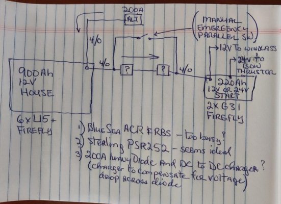
I want to wire my 200a (continuous-rated) alternator directly (with a fuse of course) to my 12v 900Ah House bank, then automate the charging connection to my 12v/24v 220Ah Start bank. Both banks have the same charging profile.
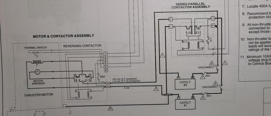
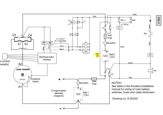
The unusual issue is that the Start bank (2xG31) is normally in 12v (parallel) configuration, but will go into 24v (series) configuration via a heavy contactor when the bow thruster is 'Activated' by a manual switch in the wheelhouse. After the thruster is de-activated, the Start bank goes back (contactor relaxes) to its normal 12v configuration for charging, engine & generator start, and windlass use.
The way the boat builder (KK) afaik dealt with the voltage disparity/bank separation issue is to have an Alternator Output Selector Switch (AOSS) manually switched between either the House or Start banks, or Both banks combined. So the boat operator MUST remember to never activate the bow thruster when the two banks are combined. Also don't try to start the engine or generator, or run the windlass when the bow thruster is activated. This system has potential for fireworks , so I want to improve it.
The attached drawing shows three possibilities. All are meant to go where the boxes with question marks are in the drawing. I'm using 4/0 in that line for an emergency engine start if Start bank was critically discharged.
Regarding possibility #2, I have an inquiry into Sterling-Power-USA whether the PSR252 https://www.sterling-power-usa.com/ProSplit-RZeroVoltDropMarineBatteryIsolator-6.aspx will withstand the Start bank in 24v configuration trying to backfeed to the 12v House bank. If it can, that seems simplest and most reliable way to do this. And it doesn't have the inefficiency/voltage drop issues of regular battery isolators.
The Blue Sea ACR (will close when charging voltage at House bank is present) and RBS (will open when bow thruster is activated) seem a bit busy (less reliable?), and the heavy diode & DC to DC charger (to deal with diode voltage drop) seem lossy and clumsy.
This is a situation I haven't dealt with before, so any constructive advice or out of the box thinking would be most appreciated.
The unusual issue is that the Start bank (2xG31) is normally in 12v (parallel) configuration, but will go into 24v (series) configuration via a heavy contactor when the bow thruster is 'Activated' by a manual switch in the wheelhouse. After the thruster is de-activated, the Start bank goes back (contactor relaxes) to its normal 12v configuration for charging, engine & generator start, and windlass use.
The way the boat builder (KK) afaik dealt with the voltage disparity/bank separation issue is to have an Alternator Output Selector Switch (AOSS) manually switched between either the House or Start banks, or Both banks combined. So the boat operator MUST remember to never activate the bow thruster when the two banks are combined. Also don't try to start the engine or generator, or run the windlass when the bow thruster is activated. This system has potential for fireworks
, so I want to improve it. The attached drawing shows three possibilities. All are meant to go where the boxes with question marks are in the drawing. I'm using 4/0 in that line for an emergency engine start if Start bank was critically discharged.
Regarding possibility #2, I have an inquiry into Sterling-Power-USA whether the PSR252 https://www.sterling-power-usa.com/ProSplit-RZeroVoltDropMarineBatteryIsolator-6.aspx will withstand the Start bank in 24v configuration trying to backfeed to the 12v House bank. If it can, that seems simplest and most reliable way to do this. And it doesn't have the inefficiency/voltage drop issues of regular battery isolators.
The Blue Sea ACR (will close when charging voltage at House bank is present) and RBS (will open when bow thruster is activated) seem a bit busy (less reliable?), and the heavy diode & DC to DC charger (to deal with diode voltage drop) seem lossy and clumsy.
This is a situation I haven't dealt with before, so any constructive advice or out of the box thinking would be most appreciated.
Attachments
Last edited by a moderator:


 .
.