Ground fault trips on shore power

The friendliest place on the web for anyone who enjoys boating.
If you have answers, please help by responding to the unanswered posts.
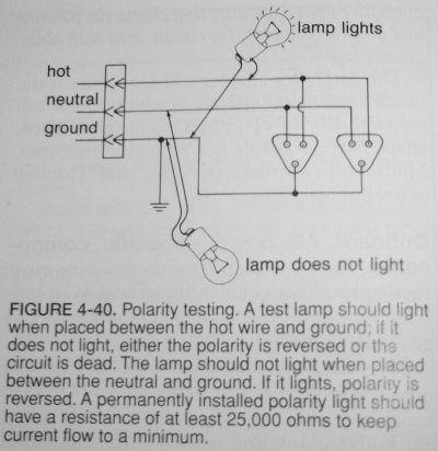
About reverse polarity indicators, they need to be 25,000 ohms minimum
I had to change mine and leave off the buzzer.
Wiring a reverse-polarity alarm - Ocean Navigator - January/February 2003
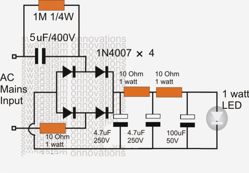
You can not just stick a pilot light in there, a neon light will work.

That's pretty much what I have been trying to say. The inherent design is a ground fault and the only way to deal with this if there is a GFCI feeding the boat is to make sure the reverse polarity circuit doesn't draw enough current to trip the GFCI.

The simple test, of course, is to disconnect the reverse polarity circuit (or lamps) and see if that solves the GFCI problem. If it does, neon or LED lamps with the appropriate resistors is your solution.

Neon lamps draw very little current and work (with a resistor) in this application, but as the article states, they don't have a long service life. The ones in my boat were dead (the green one) when I bought it at eight years and the replacements I installed are pretty much gone now, eight years later. Long ago, part of my job was servicing equipment that used neon indicating lights and replacing these was something I often had to do.

If I can find an LED light to fit my panel, that's what I will do. It's a small rectangular fixture with both red and green lights in it.
 
If the selector switch does not toggle the neutral too that could be your problem if the generator is grounded as it should be. It will be providing a leakage path to the grounding/bonding system into the water due to the neutral ground connection there. Must be a little more to it than just that though. If it is 120 volt you need to check polarity is correct on shore power switch. If hot and neutral were switched that would shut it down quick (hot to neutral grounded at generator) If 240 volt maybe an issue elsewhere on the boat.

Thanks for all the info

I suspect my problem lies with the selector switch as it does not appear to change the neutral wire (very hard to see where it is located)
Will dive into it more when I have time.

For now just replaced the breaker in the house with a non GFI unit. (It's been this way for 14 yrs with no problems)
Have a pro scheduled to come out in a week or 2
 
That's pretty much what I have been trying to say. The inherent design is a ground fault and the only way to deal with this if there is a GFCI feeding the boat is to make sure the reverse polarity circuit doesn't draw enough current to trip the GFCI.

The simple test, of course, is to disconnect the reverse polarity circuit (or lamps) and see if that solves the GFCI problem. If it does, neon or LED lamps with the appropriate resistors is your solution.

Neon lamps draw very little current and work (with a resistor) in this application, but as the article states, they don't have a long service life. The ones in my boat were dead (the green one) when I bought it at eight years and the replacements I installed are pretty much gone now, eight years later. Long ago, part of my job was servicing equipment that used neon indicating lights and replacing these was something I often had to do.

If I can find an LED light to fit my panel, that's what I will do. It's a small rectangular fixture with both red and green lights in it.

I discussed this on the 'all about circuits ' forum regarding connecting LED's to mains voltages using resistors and it was soundly condemned as a bad idea.
I went to Radio Shack and they sell red and green small neon pilot lights, they have been fine. I don't recall exactly the reasoning behind their responses on connecting LED lights to high voltage AC. At the time was looking to replace a pilot light on my AC Raritan charger using an LED bulb with resistors in series with a diode. May have had something to do with AC has these high peak to peak inverse voltage spikes.
The few LED I made up to work on 120 vac, all eventually burned out in a few weeks.

A neon light used as a reverse polarity indicator will almost never actually be on. My boat from 1970 last year finally burnt it's original light out on the Raritan charger which likely was on for 90% of those decides. I assume it was a type of neon light. It was red, and about 3/8 wide with a flat top and a translucent cover. It's 2 leads connected directly to mains voltage.
 
Last edited:
Found out the selector switch does not change over neutral wire
The neutral and grounds are hooked together on the boat some where.
Of course all the wiring is extremely difficult to access
Have a pro comming out
Will post result
Thanks
 
I wonder how many of us have this issue, and we don't know it. We went to a marina with the new system and sure enough we could not keep the dock breaker on. The boat works great with all the non new system marinas. So if you do not have a new system is there a way you can run this down without going to a new system marina? It would be great to know that you have the issue and fix it before you have guest on the boat, go to a marina with the new system and no power. Not the time for trouble shooting. IE 100 degrees, everyone is READY for AC and oh crap. Anchor out and run the Gen. Anyone have a surefire way to test the system???
 
I installed a Charles IsoBoost transformer, which eliminates the need for a polarity indicator. It also reduces the likelihood of stray voltage hazards and galvanic corrosion from other boats. A not inexpensive way of reducing some of these issues. Next up will be updating outlets.
 
I wonder how many of us have this issue, and we don't know it. We went to a marina with the new system and sure enough we could not keep the dock breaker on. The boat works great with all the non new system marinas. So if you do not have a new system is there a way you can run this down without going to a new system marina? It would be great to know that you have the issue and fix it before you have guest on the boat, go to a marina with the new system and no power. Not the time for trouble shooting. IE 100 degrees, everyone is READY for AC and oh crap. Anchor out and run the Gen. Anyone have a surefire way to test the system???

Absolutely, just plug your boat into a GFCI protected outlet, if it trips you have a problem of current leakage.
GFCI come in 240 volt versions too. My own boat, I have a 15 amp 120vac adapter to 30 amp socket, so easy for me to test it plugged into a GFCI extension cord. My boat does not trip a GFCI.

I have stove, oven, heat pump, charger, heaters, lights, many outlets, tv, vacuum cleaner, fridge, microwave, etc... It is possible some device plugged into a boat's electric could be the problem. So start a test by having all breakers off, then turn them on, then turn on each device.

You could have a wet outlet, or a salt encrusted wire causing a trip, a poorly made splice, water soaked wire, a crushed pinched wire can have a hole. A lot of wires have cloth or paper or strands of plastic inside the sheath that can wick water into them.
 
Last edited:
That is the problem in checking it. Most marinas and my home dock don't have the 50 amp GFCI outlets. Only one in our area that I am aware of.
Short of going to that marina any other method?
 
I discussed this on the 'all about circuits ' forum regarding connecting LED's to mains voltages using resistors and it was soundly condemned as a bad idea.
I went to Radio Shack and they sell red and green small neon pilot lights, they have been fine. I don't recall exactly the reasoning behind their responses on connecting LED lights to high voltage AC. At the time was looking to replace a pilot light on my AC Raritan charger using an LED bulb with resistors in series with a diode. May have had something to do with AC has these high peak to peak inverse voltage spikes.
The few LED I made up to work on 120 vac, all eventually burned out in a few weeks.

A neon light used as a reverse polarity indicator will almost never actually be on. My boat from 1970 last year finally burnt it's original light out on the Raritan charger which likely was on for 90% of those decides. I assume it was a type of neon light. It was red, and about 3/8 wide with a flat top and a translucent cover. It's 2 leads connected directly to mains voltage.

There should be both a green and a red reverse polarity light. The green will always be on if there is a ground present and will fail in a few years if it's neon. No green light? Missing ground, a dangerous situation.

West Marine sells 120 volt AC LED pilot lights with the resistor built in.

And if you asked for technical advice at Radio Shack, that was your first mistake. The sales people are not engineers, they are not technicians, they are people who scan items and tell you how much you owe. Nothing more.

No, I dont ask for tech advice from RS. I just have red lights for a reversal indication, no green ones a-ok, although I could add them. Boat OEM had only those.

Here is a circuit designed to keep LED connected to main voltages from eventually burning up, if you want it to last for years.
http://www.homemade-circuits.com/2012/03/how-to-make-simplest-1-watt-led-driver.html

1%2Bwatt%2Bled%2Bdriver%2Bcircuit.png
 
Last edited:
Problem solved!
The inverter has a relay that switches the neutral wire when the inverter is switched on,
When there is no power to the inverter I.E.: no shore power, it defaults to "inverter mode" which connects ground and neutral (as it should) the problem occurs when the shore power is first connected the transfer relay is in inverter mode which immediately blows ground fault.
We isolated all the inverter load neutrals to a separate bus and no more problems.
Thanks for all the input.
 
Last edited by a moderator:
No, I dont ask for tech advice from RS. I just have red lights for a reversal indication, no green ones a-ok, although I could add them.

The green one tells you there is an actual ground (not open) so that's kind of important as well.

I suppose one could build a protective circuit for the LEDs, but West Marine sells nice compact ones for just a few dollars each. Hook up the two wires and you're done. Everything is in the package.
 
The green one tells you there is an actual ground (not open) so that's kind of important as well.

I suppose one could build a protective circuit for the LEDs, but West Marine sells nice compact ones for just a few dollars each. Hook up the two wires and you're done. Everything is in the package.

That's the one thing I have not done yet is reconnect the reverse polarity light
Will post if I have a problem with that, for now all good
 
Many of the panels I have worked on and the Blues Seas ones I just checked on line (wiring diagrams))...

I thought the green LED just means you have shore power and the main breaker is on.

Maybe that means that the ground is good...but that light is just wired to hot and neutral.....

I must be missing something as shouldn't that light work whether there is a ground or not?

It's supposed to he from hot to ground. That way you know you have a ground but that's also why you need neon or LED indicators to avoid a ground fault trip with a GFCI breaker.

Hot to neutral says you have power but doesn't check for a ground.
 
Problem solved!
The inverter has a relay that switches the neutral wire when the inverter is switched on,
When there is no power to the inverter I.E.: no shore power, it defaults to "inverter mode" which connects ground and neutral (as it should) the problem occurs when the shore power is first connected the transfer relay is in inverter mode which immediately blows ground fault.
We isolated all the inverter load neutrals to a separate bus and no more problems.
Thanks for all the in put.

Glad to hear you have identified the problem.

Wonder if a certain critic of mine might be willing to give me a little credit on this one. :rolleyes:

If the selector switch is to off, main breakers are off, then the neutral and positive are supposed to be open. Only not open shore power wire is the ground. Seemed like a good place to start.

What's your suggestion?

Ted

I understand that. Some times you see ground and neutral tied together.

Ted

The ground is not in the GFI circuit. The GFI measures between hot & neutral.
A GFI or any AC outlet will work without a ground (until there's a problem :)
Could be a Chinese GFI, lots of fakes out there and a couple of major recalls. You never get enough info on these types of posts to offer a definitive answer.

Look BP, I'm not saying it's ok to do, I'm saying these are things you can look for that might explain it on the boat end.
Ted

Ted
 
It's supposed to he from hot to ground. That way you know you have a ground but that's also why you need neon or LED indicators to avoid a ground fault trip with a GFCI breaker.

Hot to neutral says you have power but doesn't check for a ground.
Well...you might want to write Blue Seas as that is how they are wired at the factory.
 
It's supposed to he from hot to ground. That way you know you have a ground but that's also why you need neon or LED indicators to avoid a ground fault trip with a GFCI breaker.

Hot to neutral says you have power but doesn't check for a ground.

Like psneeld wrote "Well...you might want to write Blue Seas as that is how they are wired at the factory."

Here is the Blue Seas factory wiring diagram for the #8467 AC Panel on my boat. Those green LED's on the main breakers are definitely wired from hot to neutral.
 

Attachments

  • Blue Sea 8467 - AC Panel Wiring.JPG
    Blue Sea 8467 - AC Panel Wiring.JPG
    71.9 KB · Views: 69
I'll get right on it. :banghead:

I actually forgot, I do have a green panel light, it is LED and wired from hot to neutral.
I also have 2 digital AC gauges with voltage and amps, one for each 30 amp shore line. Amps are measured with a sense coil that slips over the wire. They both light up when power is on.
The green light mostly guarantees I have AC power running to the charger, and the panel gauges that I have power running to the distribution panel for each 30 amp line.

Code wise, ground is never supposed to carry any current.
 
Last edited:
Well...you might want to write Blue Seas as that is how they are wired at the factory.

After some research, it seems you are confusing a simple pilot or "power on" light with a reverse polarity indicating system.. They are not the same. A pilot light is a nice convenience feature but it is not a safety system.

I have attached two diagrams. On the left is a portion of the actual electrical schematic from my boat. It may be a bit difficult for a layperson to follow because it is a schematic, not a picture of where to connect the wires.

Following the lines, we see that the "OK" light is connected to the line side of the "hot" master breaker and the other terminal of the light is connected to the ground block.

The "REV" light is connected to the line side of the neutral master breaker and the other terminal is also connected to ground (because the lights share a common ground connection).

The light assembly consists of a red and a green neon lamp along with their individual series limiting resistors. Because of the limiting resistors, this circuit should not cause nuisance tripping of a shore GFCI breaker.

On the right is a photo from a Nigel Calder electrical book showing a simplified version of the same circuit. This circuit will test for a reverse polarity or open ground situation, but as drawn, would trip a GFCI. As stated in the caption, series resistors would need to be installed to avoid this problem.


BTW: The most popular accompaniment for crow is hot sauce. Lots of hot sauce.
 

Attachments

  • circuit 002.jpg
    circuit 002.jpg
    133.4 KB · Views: 63
  • circuit 009.jpg
    circuit 009.jpg
    115 KB · Views: 67
Last edited:
After some research, it seems you are confusing a simple pilot or "power on" light with a reverse polarity indicating system.. They are not the same. A pilot light is a nice convenience feature but it is not a safety system.

I have attached two diagrams. On the left is a portion of the actual electrical schematic from my boat. It may be a bit difficult for a layperson to follow because it is a schematic, not a picture of where to connect the wires.

Following the lines, we see that the "OK" light is connected to the line side of the "hot" master breaker and the other terminal of the light is connected to the ground block.

The "REV" light is connected to the line side of the neutral master breaker and the other terminal is also connected to ground (because the lights share a common ground connection).

The light assembly consists of a red and a green neon lamp along with their individual series limiting resistors. Because of the limiting resistors, this circuit should not cause nuisance tripping of a shore GFCI breaker.

On the right is a photo from a Nigel Calder electrical book showing a simplified version of the same circuit. This circuit will test for a reverse polarity or open ground situation, but as drawn, would trip a GFCI. As stated in the caption, series resistors would need to be installed to avoid this problem.


BTW: The most popular accompaniment for crow is hot sauce. Lots of hot sauce.

However, connecting a neon or LED permanently from hot to ground and the light lights up does not tell you if that ground can carry any significant current. You could have a very high resistance in the ground wire that will light the bulb just fine, but not function as a safety ground, so a false sense of security that the ground is a good ground.

And ground is never supposed to carry any currents in normal operation.
That's a valid point but in practice there's a limit to what testing we can do each time we pull into a new marina. If we were to impress a full 120 volts on the ground conductor as a test, it could damage other boats on the same circuit and injure or kill anyone who happens to be working on the equipment. The neon lamp provides the same level of testing as the $10 outlet testers from the home center.

Agreed, the ground conductor is not supposed to carry current, it's only there for safety.
 
Last edited:
That's a valid point but in practice there's a limit to what testing we can do each time we pull into a new marina. The neon lamp provides the same level of testing as the $10 outlet testers from the home center.

Agreed, the ground conductor is not supposed to carry current, it's only there for safety.

If you could connect say a high amp load like a vacuum cleaner, etc.. temporarily between the hot and the ground, that will tell you if your ground is a good ground. Knowing you have a good ground on a boat would be a good idea. Not that i actually check it myself, I just assume it is, but that might be a tragedy waiting to happen. At least all my outlets are GFCI.
 
Last edited:
If you could connect say a high amp load like a vacuum cleaner, etc.. temporarily between the hot and the ground, that will tell you if your ground is a good ground. Knowing you have a good ground on a boat would be a good idea. Not that i actually check it myself, I just assume it is, but that might be dangerous.

I edited my post while you were posting yours. Read it again.
 
I edited my post while you were posting yours. Read it again.

The marina electrical ground system should be the lowest resistance path for current, so should not create a lethal hazard. Otherwise, overload the amps so breaker does an instantaneous trip. Done that plenty of times by accident.
 
The marina electrical ground system should be the lowest resistance path for current, so should not create a lethal hazard. Otherwise, overload the amps so breaker does an instantaneous trip. Done that plenty of times by accident.

We assume it is and so does the green test light. If it is open (and that's our concern) we can damage equipment or harm people. I don't think we want to intentionally connect it to power.
 
After some research, it seems you are confusing a simple pilot or "power on" light with a reverse polarity indicating system.. They are not the same. A pilot light is a nice convenience feature but it is not a safety system.

I have attached two diagrams. On the left is a portion of the actual electrical schematic from my boat. It may be a bit difficult for a layperson to follow because it is a schematic, not a picture of where to connect the wires.

Following the lines, we see that the "OK" light is connected to the line side of the "hot" master breaker and the other terminal of the light is connected to the ground block.

The "REV" light is connected to the line side of the neutral master breaker and the other terminal is also connected to ground (because the lights share a common ground connection).

The light assembly consists of a red and a green neon lamp along with their individual series limiting resistors. Because of the limiting resistors, this circuit should not cause nuisance tripping of a shore GFCI breaker.

On the right is a photo from a Nigel Calder electrical book showing a simplified version of the same circuit. This circuit will test for a reverse polarity or open ground situation, but as drawn, would trip a GFCI. As stated in the caption, series resistors would need to be installed to avoid this problem.


BTW: The most popular accompaniment for crow is hot sauce. Lots of hot sauce.

I know exactly how these systems work...and I can read basic schematics.

However, I had never seen a green "good ground light" on any boat I have been on and was responding how the permanent green lights on most panels work. Like Blue Seas. These are actual panels and not a drawing in a book. Green usually just means plugged in, breakers on.

Was just pointing that out to the many boaters who might have thought the green light on their panel meant they had a good ground....or even more so, that they were even wired that way. Post 49 clearly shows the way most are wired...green just means power, nothing about grounds..

I would think a full time indicating light, not a temporary test light is a current carrying ground wire....no matter how small the amperage. Till I see it differently in ABYC or other set of codes, I will just watch the crows to see where they land.
 
Last edited:
Back
Top Bottom