Galvanic isolator with an Inverter

The friendliest place on the web for anyone who enjoys boating.
If you have answers, please help by responding to the unanswered posts.

CEC

Senior Member
Joined
Apr 3, 2018
Messages
125
Location
USA
I'm wanting to know the correct place for my galvanic isolator when using an inverter. Very straight forward setup:

Shore powers going to the inverter with built in transfer relay and breakers. From there it goes out to the main panels 30 amp breaker. Currently the galvanic isolator is on the ground/green wire at the main panel bypassing the 30 amp main panel breaker and going out right to the ground bar.

I'm wondering if its better to have it closer to the inverters out or leave it at the main panel where its at. There's a 8' run between the shore power connection and the inverter then another 8' from inverter to the main panel. I don't believe it should be before the inverter, but I could be wrong (that's happened before :).

I don't see this in the codes or in the galvanic isolator's manual, or in the inverters manual. Its easy enough to move, but I don't want to if it makes no difference. I also don't want to fry it as it was not cheap..
 
I think you want the galvanic isolator as close to the shore power inlet as is reasonably possible given the need to keep it dry, etc.

In some sense, it doesn't matter where it is, as long as it isolates the boat's ground from the earth ground(*), thereby preventing your boat's zincs (or less noble metals in useful components!!!) from getting consumed protecting your neighbors' boats that share the same earth ground.

There may be other reasons that aren't coming to my mind, but i think the big reason one wants it close to the shore inlet is just to prevent it from accidentally getting bypassed. If any ground bypasses it, by intention or accident, since they are all tied together, everything has bypassed it.

(*) One does want the boat's ground to be tied to the shore ground for safety reasons, which is why the galvanic isolators only isolate up to ~1.4V -- allowing the ground to function normally for safety beyond that. In this way, they provide isolation for the low voltages stray currents that cause corrosion -- but a ground path for the high voltage electrical problems that could otherwise kill someone.
 
Last edited:
Hello CEC,
If it was my boat, I (a residential / commercial electrician with 20 years + experience) would try get the best professional answer to your galvanic isolator question. One person i would ask would be, Steve D' Antonio asksteve@stevedmarineconsulting.com.
Great wealth of marine knowledge can be found on Steve's website :thumb:
 
I'm wanting to know the correct place for my galvanic isolator when using an inverter. Very straight forward setup:

Shore powers going to the inverter with built in transfer relay and breakers. From there it goes out to the main panels 30 amp breaker. Currently the galvanic isolator is on the ground/green wire at the main panel bypassing the 30 amp main panel breaker and going out right to the ground bar.

I'm wondering if its better to have it closer to the inverters out or leave it at the main panel where its at. There's a 8' run between the shore power connection and the inverter then another 8' from inverter to the main panel. I don't believe it should be before the inverter, but I could be wrong (that's happened before :).

I don't see this in the codes or in the galvanic isolator's manual, or in the inverters manual. Its easy enough to move, but I don't want to if it makes no difference. I also don't want to fry it as it was not cheap..


Unlike a fuse or circuit breaker which should be as close to the source of power as possible, a Galvanic Isolator can be anywhere in the ground wire between the shore power ground and the first ground connection to the boat. It MUST be installed before any ground connection to the boat or you defeat how it works.


Ken
 

Attachments

  • Isolator.jpg
    Isolator.jpg
    87.3 KB · Views: 230
Ken explained it correctly. I will add only one thing. The purpose of the isolator is to prevent low voltage induced DC currents existing on the shore power ground connection. It has nothing to do with any inverter or any other power source on the boat.
 
Thank you all for the answers. I’m going to leave it where it’s at. It’s great to have confirming feedback to help with reinforcing even a professionals opinion. There’s no other boat connection to the inverter, so the isolator will remain before the boat panels connection.

Moving it closer to the out of the isolator gets me nothing.

Putting it before the inverter would just open me up to no isolation when the inverter is in use so that’s not correct.

Thanks again.
 
CEC,

Just to make sure...

Metals have different electrode potentials. Some of them are more reactive (less noble), others less reactive (more noble). When dissimilar metals are in an electrolyte like salt water, more active metals form positively charged anodes, less active metals form negatively charged anodes. The electrolyte carries the ions from the anode to the cathode, destroying the anode. This current flow between metals through an electrolyte is basically how a battery works.

Our boats basically suffer from the same thing. They are a bunch of dissimilar metals floating in salt water. As a result the salt water conducts ion flow among the metals, corroding the more active (less noble) ones. This is why we attach zincs to our boat. zinc is very active, so it'll supply ions to the other metals, so the metals we care about aren't donors, and don't corrode.

Since our boats are tied to earth ground via the ground wire on shore power, we can get these currents flowing among boats. That means that one boat's zincs can end up protecting another boat. Or, worse, one boat's bronze can get dezincified, becoming less dense and spongy, slowing the corrosion of another boat.

Galvanic isolators work by disconnecting our boats from the earth ground. Thus, our boat only needs to protect our boat. One could do this just by leaving the ground wire "open" -- but that would be dangerous for the humans it protects. So, what these galvanic isolators do is use a couple of diodes, or something like that, to allow the ground to be open for low voltage DC currents -- so we aren't protecting other boats -- but to switch closed for high voltages, so we are protected from electrical hazards.

The reason I mention this is that, when your boat is running on the inverter it is most likely completely disconnected from shore power, e.g. while underway. Because it is disconnected from shore power, it is protected from this type of corrosion, anyway. The ground wire isn't attached to shore. The exception would be if you have the shore power breaker turned off and are running off the inverter, but the cable is still connected -- the breaker only interrupts the hot wire, not the ground wire.

When I mention running off the inverter, I don't mean the inverter's transfer relay is activated to power the boat from shore power. Insead what I mean is that the inverter is supplying AC power from DC power, because there is no shore power (and further, that shore power is completely disconnected).

The only important thing about the galvanic isolator is that it break that connection between the boat's ground and shore ground (for low voltages). It can be anywhere that lets it do that and work effectively. The only thing is, the deeper it gets installed into the system, the easier it is for someone to accidentally or unknowningly install something that bypasses it.
 
One point, a galvanic isolator does not disconnect the ground wire from shorepower, it puts one or 2 diodes in the line to provide up to about 1.5V of isolation between the boat's ground and shorepower ground. This voltage level is more than tyical galvanic voltages, hence the "galvanic isolation". Even with a galvanic isolator installed, a true power to ground fault will still allow the ground fault current to be able to be conducted to ground.


Ken
 
Hi Ken,

If that was directed to me, I think I had it burried in there. I probably should use fewer words for clearer meaning :)

"So, what these galvanic isolators do is use a couple of diodes, or something like that, to allow the ground to be open for low voltage DC currents -- so we aren't protecting other boats -- but to switch closed for high voltages, so we are protected from electrical hazards. "

Cheers!
-Greg
 
Last edited:
I just realized in reading back through the thread that in my original reply in one place I wrote "stray current" when I was talking about galvanic action. That was a bit of a finger slip.

Stray current is when current, usually intended to be part of an electrical circuit, is returning via the boat's metal fittings and the water. The classic example is that the wiring for a bilge pump falls into the bilge and, although some current runs through the intended circuit -- some leaks through a wet connection into the water in the bilge, and then completes the circuit via the boat's metal fittings and the water. These currents can cross boats -- but most often don't. "The one who smelt it dealt it".

Because these tend to be 12V circuits (or 24V circuits) their voltages are way higher than the millivolts of galvanic action and they tend to be dramatically more damaging dramatically faster than the much smaller galvanic currents of galvanic action. They can burn right through whatever metal allows them to leave the vessel, e.g. turn a thru-hull into a hole.

Galvanic isolators are of no protection. Zinc anodes are of very little protection. A good bonding system can slow the damage only by spreading it out over much more metal so all of the metal corrodes more slowly instead of a little super fast.

Sorry if I caused any confusion.
 
Hi Ken,

If that was directed to me, I think I had it burried in there. I probably should use fewer words for clearer meaning :)

"So, what these galvanic isolators do is use a couple of diodes, or something like that, to allow the ground to be open for low voltage DC currents -- so we aren't protecting other boats -- but to switch closed for high voltages, so we are protected from electrical hazards. "

Cheers!
-Greg


I didn't mean any disrespect, but I wanted to make sure it was clear that even with a galvanic isolator installed, there still was a path to safety ground for fault currents.


Ken
 
My main concern was the inverter and it’s transfer relay. When reading the manual it indicates three wires into its block from shore power and two only hot and neutral coming out. You then connect the ground to a different screw on the inverter that then goes to the boats ground.

What was worrying me was that ground but further reading explains there’s a ground relay that flips between shore power and inverter power. It’s a separate relay from the transfer relay but I think it’s tripped by the transfer relays position.

It moves the ground connection between closed for shore power when connected to open when on inverter power.

This is why I was considering the location of the isolator before or after the inverter. Leaving it we’re its at in the main panel is best I think because it’s a visual reminder./indicator. My fear is the inverter might hurt the isolator somehow but I think I’m overthinking it. Seems it’s really not doing anything when on inverter power.

Thanks there’s a lot of great explanations in this thread.
 
CEC
Do you have an inverter bypass switch installed?
 
CEC,

Someone earlier in the week (Maybe Sunchaser?), I think on a different thread, mentioned using the Blue Sea Systems rotary switch for an inverter bypass switch.

I took a look at the Blue Sea Systems 9009 (1481 with panel) to see what it switched and how:
-- https://www.bluesea.com/products/9009/AC_Rotary_Switch_-_OFF_+_2_Positions_120V_AC_30A

Since the wiring wasn't posted in that thread, I started to quickly throw together a potential wiring schematic to post. But, I never got around to double checking it and I lost the thread and had to erase my whiteboard before I got back to it. So, I'll post it here.

But, please, let's take it for what it is: A 4 minute fast sketch that might have errors. A scribble I started to do over lunch one day. Please no one use it without careful thought and checking.

The good news is, I suspect it won't take long for folks here to correct any mistakes! :)

Edit: Looking at my post, I realized I drew the isolation transformer's output-side ground wrong internal to the transformer. I just photoshopped it and fixed it.
 

Attachments

  • 0424192202.jpg
    0424192202.jpg
    61.7 KB · Views: 137
Last edited:
CEC,

Someone earlier in the week (Maybe Sunchaser?), I think on a different thread, mentioned using the Blue Sea Systems rotary switch for an inverter bypass switch.

I took a look at the Blue Sea Systems 9009 (1481 with panel) to see what it switched and how:
-- https://www.bluesea.com/products/9009/AC_Rotary_Switch_-_OFF_%2B_2_Positions_120V_AC_30A

.

Yup, that is the style I mentioned. Very common and advertised by Blue Seas and vendors as an inverter bypass switch. The marine tech I frequently use said he has installed dozens of rotary bypass switches over the years. Mine is mounted adjacent to the Magnum 2800.
 
Hi all,

Actually, I *really* want to revise my prior post. As I look more at it, I don't like it at all. I wouldn't wire my boat that way. I was originally concerned that a cut-off switch was an unnecessary complexity and tried to avoid it. But, I now think it is essential.

One thing about the first sketch is that I have the 30A main breaker feeding the bypass switch. This has me double-tapping that breaker, which isn't good in general. Specifically, in this case, it would mean that a problem on the feed leading to the inverter-charger or with the bypass switch could disable the main AC panel, even on shore power. Less important, it would mean that the wiring would need to be rated for the full 30A, all the way along the path to the inverter panel. Basically, drawing it this was was a mistake. I didn't think it through.

I'd rather wire it as attached. This does require an extra cut-off switch, but so be it. And, it requires the inverter's input and output wiring be rated for at least the same current as the inverter-charger's breaker, but that is okay.

Looking at the sketch, we see that the same rotary switch is going to power the inverted-load panel and bus from either the inverter's input circuit or the inverter's output circuit, thus it acts as a bypass. This put it on a nice 15A or 20A breaker (or whatever is required) in the circuit, either way. The rotary switch acts as a cut-off for the inverter's output, by disconnecting it when the switch is OFF or selecting shore power as the source.

I've drawn a cut-off switch on the input of the inverter/charger. This is essential for the case where the charger is popping the breaker or boiling the batteries, or otherwise misbehaving.

This drawing provide proper circuit protection for everything, avoids having the same breaker protect two different things at the same time, and enables the charger-inverter to be completely removed from the system.

I'm also now imaging a situation where I wanted to run the inverted-load panel off of the house main in order to let the house batteries charge faster. In this case, I would want the rotary switch to select the shore power as the input without opening the inverter-charger's input cut-off. This would mean that the combined load of the inverter-charger charging and the inverted load panel couldn't exceed the breaker. That might work out okay if the device load was load enough on the panel.

Otherwise, the way to adjust things would be to run another AC circuit, with its own breaker, to use for the bypass instead of allowing it to be shared between the inverted-charger-load and the inverter input. This would then mean that the extra cut-off switch wouldn't be needed -- the inverter-charger's input breaker would serve that purpose, as it always has. I actually like this approach better and I would prefer it, a slot for a breaker available.

Again, my own boat doesn't have a bypass and I've never installed one. So, I'm just thinking this all through for the first time in between a bunch of other things. But, having read these conversations recently, I think I'll put adding one "on the list". :)

I just worked on this for a very few minutes in between doing some other things. So, I could have goofed up again. None-the-less, I trust the crowd to let me know!

Cheers!
-Greg
 

Attachments

  • 0425190047.jpg
    0425190047.jpg
    60.1 KB · Views: 123
Last edited:
Thanks for the info on the switch. All I really desire is the ability to bypass the inverter in the event it breaks down or I need to replace it ext. Currently I’d be doing a lot of wire work to retain shore power if the inverters transfer relay was not working. The simple 3 way rotary will do the trick it looks a bit awkward so finding a spot for it will be the next hurdle.
 
If I'm understanding you correctly, your galvanic isolator is connected AFTER your inverter. I'm assuming your inverter was not original equipment, and sounds like a Victron. It actually doesn't matter the brand or type of inverter, but your GI needs to be just after the shore power inlet, before ANY device. If it's connected at your panel, after the inverter, it needs to be moved or it is useless.
 
Hello CEC,
If it was my boat, I (a residential / commercial electrician with 20 years + experience) would try get the best professional answer to your galvanic isolator question. One person i would ask would be, Steve D' Antonio asksteve@stevedmarineconsulting.com.
Great wealth of marine knowledge can be found on Steve's website :thumb:

Thank you for the kind words.

As some others have already noted, the correct placement for a galvanic isolator (GI) is between the shore inlet and the electrical panel. While it's not mandatory to place it close to the inlet, that's advantageous in that it makes it less likely that a AC safety ground or binding wire is, or will be, tapped into this wire between the GI and the inlet. If that happens, it essentially bypasses the GI, rendering it useless. Electrically, nothing must come between the GI and the inlet. This article covers the subject https://stevedmarineconsulting.com/galvanic-isolators-and-zinc-anode-selection/

Whether or not you have an inverter is irrelevant, the GI must be placed so that nothing is between it and the AC safety ground connection at the shore inlet.

As far as GI selection goes, make certain it meets ABYC A-28 revision 2008. I do encounter inexpensive non-compliant GI's in the field, and still being sold. It does not need monitoring if it meets this "fail safe" standard, which means if it fails it does so in the closed or conducting condition, which provides the necessary degree of safety, but no galvanic isolation (the lesser of two evils).

(Currently in Taiwan inspecting a new build)
 
CEC,

Just to make sure...

Metals have different electrode potentials. Some of them are more reactive (less noble), others less reactive (more noble). When dissimilar metals are in an electrolyte like salt water, more active metals form positively charged anodes, less active metals form negatively charged anodes. The electrolyte carries the ions from the anode to the cathode, destroying the anode. This current flow between metals through an electrolyte is basically how a battery works.

Our boats basically suffer from the same thing. They are a bunch of dissimilar metals floating in salt water. As a result the salt water conducts ion flow among the metals, corroding the more active (less noble) ones. This is why we attach zincs to our boat. zinc is very active, so it'll supply ions to the other metals, so the metals we care about aren't donors, and don't corrode.

Since our boats are tied to earth ground via the ground wire on shore power, we can get these currents flowing among boats. That means that one boat's zincs can end up protecting another boat. Or, worse, one boat's bronze can get dezincified, becoming less dense and spongy, slowing the corrosion of another boat.

Galvanic isolators work by disconnecting our boats from the earth ground. Thus, our boat only needs to protect our boat. One could do this just by leaving the ground wire "open" -- but that would be dangerous for the humans it protects. So, what these galvanic isolators do is use a couple of diodes, or something like that, to allow the ground to be open for low voltage DC currents -- so we aren't protecting other boats -- but to switch closed for high voltages, so we are protected from electrical hazards.

The reason I mention this is that, when your boat is running on the inverter it is most likely completely disconnected from shore power, e.g. while underway. Because it is disconnected from shore power, it is protected from this type of corrosion, anyway. The ground wire isn't attached to shore. The exception would be if you have the shore power breaker turned off and are running off the inverter, but the cable is still connected -- the breaker only interrupts the hot wire, not the ground wire.

When I mention running off the inverter, I don't mean the inverter's transfer relay is activated to power the boat from shore power. Insead what I mean is that the inverter is supplying AC power from DC power, because there is no shore power (and further, that shore power is completely disconnected).

The only important thing about the galvanic isolator is that it break that connection between the boat's ground and shore ground (for low voltages). It can be anywhere that lets it do that and work effectively. The only thing is, the deeper it gets installed into the system, the easier it is for someone to accidentally or unknowningly install something that bypasses it.

Much if what you have said here is correct, and good advice, but some points need clarrification.

You cannot dezincify bronze, by definition it has little or no zinc as a constituent element. Copper alloys that contain zinc are by definition brass. If you are relying on galvanic isolation or cathodic protection to prevent dezincification of anything other than a propeller, many are manganese bronze, which is actually brass, then you are asking for trouble. Alloys used underwater, which would allow flooding if they failed, i.e. plumbing, seacocks, fasteners etc, should never be brass, and ideally they should contain little or no zinc. Leaded red brass, commonly used to make pipe nipples, is allowed up to 15% Zn, the less the better. The problem is, it's impossible to know by looking at any allow how much zinc it contains other than the more zinc it contains, the more yellow it is in color, but that's hardly scientific.

This article covers dezincification: https://stevedmarineconsulting.com/know-your-underwater-alloys/

This one covers galvanic corrosion: https://stevedmarineconsulting.com/unraveling-the-corrosion-mystery/

GI's don't disconnect the boat from earth ground, they prevent the flow of DC current (that's where the diodes come in) which causes galvanic corrosion, while allowing all important AC fault current to flow, this is necessary for safety, and not just electrocution protection but for fire prevention as well. From an article on the subject "Galvanic isolators block DC current (at up to 1.4 volts DC across the isolator, anything above that is beyond galvanic corrosion potential), which is what causes corrosion, while allowing AC current, including the all too important shore power faults, to pass. Blocking DC current means that when you plug into shore power your vessel is now isolated from other vessels’ AC grounds and bonding systems, and you are no longer protecting your slip neighbor’s boat that hasn’t had its anodes changed in two years (i.e. you are not paying for his protection using your anodes)."

Full article here https://stevedmarineconsulting.com/galvanic-isolators-and-zinc-anode-selection/


Allowing fault current to return to its source (contrary to popular belief it does not seek ground, it seeks to return to its source, which in the case of a dock is usually the transformer at the head of the dock), in the event of a fault and no low resistance return path, that may be through the water (which can cause electrocution or electric shock drowning/ESD). When a fault occurs the low resistance path back to its source is what trips the circuit breaker, rendering it safe. This is why the AC shore safety ground is so vitally important, and why nothing can be placed in its path other than (an ABYC A28-compliant) galvanic isolator.

In short, every vessel that has shore power should, if it's ever plugged in, have a complaint galvanic isolator.
 
If I'm understanding you correctly, your galvanic isolator is connected AFTER your inverter. I'm assuming your inverter was not original equipment, and sounds like a Victron. It actually doesn't matter the brand or type of inverter, but your GI needs to be just after the shore power inlet, before ANY device. If it's connected at your panel, after the inverter, it needs to be moved or it is useless.

Inverter is a magnum and it has built in transfer relays for power and ground. The isolator is connected on the ground coming out of the inverter before going to the ground bar for the boat. That ground is only connected when on shore power. The inverter is connected to the main panel breaker. No ground is connected to the boat from shore power before the inverter wether on shote power or inverter power.
 
Confusing wording flips the meaning

CEC,

Just to make sure...

So, what these galvanic isolators do is use a couple of diodes, or something like that, to allow the ground to be open for low voltage DC currents -- so we aren't protecting other boats -- but to switch closed for high voltages, so we are protected from electrical hazards.


I would like to clarify that the above sentence of Ken is understandable only if you replace the word "open" by isolated and the words "switch closed" by let pass through. For most people the word switch closed means switch is off = connection cut. But I believe Ken means the connectors are connected. And before when saying "open for low voltages" we know that low voltage MUST NOT get through, so connection is cut open. NOT meaning the isolator is open to let the low voltage through.:blush:


It is a small thing which I dont know did anyone else stumbe on this but it caught my attention as it seemed like contradicting with what Ken had just said in the previous post.

Just to be clear, I was not the person who said that. Also, I agree with you completely that using the word "open" in any sense when describing the behavior of a galvanic isolator is very misleading at best. isolators do indeed use diodes in series with the ground wire, but the ground is never disconnected, it merely has a semiconductor device inserted in the ground that requires a voltage of typically 1.5-2V before it will start to conduct.

Ken
 
Hi all,

I'll own that.

I apologize. I simplified a galvanic isolator as being a switch in an early message in the thread. I didnt want to get into the details of saturating PN junctions and capative coupling passing AC but not DC stray current. It seemed to be too much to answer the original question. Im learning not to round too many corners on this forum!

A more loyal model would have been to describe it as two pairs each of two diodes and a capacitor, with each pair of diodes and the capacitor wires in parallel.

The two diodes in each pair oriented in series in the same direction such that they combine to require about 1.4V, 0.7V each, to saturate, preventing lower voltage stray currents from biasing the pair of junctions and passing current. The two pairs are oriented in parallel, but in opposing directions, such that each AC phase has a path. The parallel pairs of diodes are in parallel with a capacitor or capacitors, which allows AC to pass, but not DC stray currents, such that the AC safety ground contines to function sufficienyly even in the event of diode failure.

Real world implentations may be more sophisticated. I've never taken one apart or modelled one w.r.t. heat dissipation, loss in coupling or anything else. One day in my spare time...
 
The isolator is connected on the ground coming out of the inverter before going to the ground bar for the boat. That ground is only connected when on shore power. The inverter is connected to the main panel breaker. No ground is connected to the boat from shore power before the inverter wether on shote power or inverter power.

Two questions:
-- Is this rationale at odds with Steve D's recommendation for GI location in post 21?
-- Assuming your GI location preference, when inverter is bypassed is GI functionality still in place?

Our vessel has two GIs, each located within 8" or so of the hull incoming shore feed receptacle and before the electric panel.
 
Hi Steve, Hi all,

Steve: Thanks! I did confuse brass and bronze in what I wrote! I appreciate you taking the time to make that right!

As for diodes switching on and off or open and closed, I am sorry I used that language in that post. It apparently wasn't at all helpful and, from the reactions I've gotten, has been quite the distraction! Having said that, I actually think it was correct (be it totally unhelpful). So, for anyone curious, I am going to explain it. If I'm wrong -- I'm all ears. Pretty please do let me know. I don't deal with things at this level of detail very often. My model could have been corrupted at some point and I just don't realize it. I'd much rather learn than continue to be wrong about it.

My model of a diode includes a P(anode) region and an N(cathode) region. In the N region there are some covalent bonds among the materials in the lattice that leave electrons unbound and in the P region, there are some covalent bonds in the lattice that are missing electrons. These are the results of secondary materials that off balance things being "duped" into the lattice. The imbalance that results from the free electrons (extra electrons) and free holes (missing electrons) is balanced out by much weaker ionic bonds (opposites attracting versus sharing of electrons between atoms). The N side and the P side can each have N and P imbalances that go both ways, but the N side has more favoring free electrons and the P side has more favoring missing electrons (holes).

Without some more magic, this wouldn't matter much because, even if by a mixture of bond types, the N side and the P side are each neutral in charge. There is no electrical or magnetic force acting between them. But, by careful manufacturing what can happen is that some of the free electrons, being weakly connected anyway, are able to be pulled over the border by "opposites attracting" and fill in the holes on the other side. This starts to generate a region where the two come together that is out of balance. It is relative positive where the electrons left and relatively negative where the holes got filled. There is only so much force pulling, so eventually enough electrons cross over that they manage to repel other electrons from coming over (opposites attract, but sames repel). And, given the distances, this happens pretty quickly, making for a relatively thin "cross over" zone.

These weakly connected electrons and available holes are known as "charge carriers" because they allow current to flow. When motivated by potential energy (voltage), electrons can jump, leaving a hole where they left and filling one where they go to. This is why electron flow and hole flow are said to be opposites. As an electron moves one way, a hole seems to move the other.

But, back to the diode. With this movement, something interesting has happened. We've ended up with this thin area between the P region and the N region that is depleted of available charge carriers. For this reason, it is sometimes called the "depletion zone". It also has a local charge to it, owing to the imbalance. For this reason it is sometimes called the "space charged zone" There is actually "potential difference" (voltage) across it because of that imbalance. But, at least at rest, there is no current flow, because everything that could flow did.

This local potential difference is sometimes called the built-in voltage of the diode and symbolized Vbi. It is somehow related to the voltage drop of the diode that we all know and love, e.g. about 0.7V for silicon diodes. I'm going to wave my hands and rhetorically suggest asking William Shockley. I don't know the relationship between the two, and don't think I ever did. The only thing I remember is that the threshold voltage drop varies with the current flow and temperature and some other parameters, but so very little that it doesn't matter within the application space of the device.

Regardless, back to that threshold voltage. What happens if we apply a "forward voltage" to a diode, i.e. generate an imbalance with electron donors on the N side and holes on the plus side? For low enough voltages, absolutely nothing we can see from the outside. The potential differences asserts a fore that overcomes some of the "opposites attracting" thing and the depletion zone gets smaller. But, current still can't flow at all -- because the depletion zone still exists and it is an insulator. But, at a certain point, we apply enough of a voltage to overcome the opposites attracting thing, the depletion zone collapses....and now we have an area with free electrons directly up against one with free holes and a potential difference across them. Like magic, we've got a bunch of electrons being driven to hope from hole to hole to hole. We've got current flow!

Even after current starts to flow, the voltage drop doesn't go away, because it is still pushing against the imbalance that created the depletion zone at the PN junction. But, as many electrons go in one one side as come out the other. And, the opposite is true: As many holes appear on one side as disappear from the other. Once a diode switches on, it is on, it does not limit current flow.

This is why I referred to a forward biased diode at or above Vth as being like a switch that is "closed" or "on" and otherwise being like a switch that is "open" or "off". Like a switch in the "On" state, a diode above Vth allows unrestricted current flow, and otherwise, like a switch in the "off" state, allows none.

Does it work exactly like this? Well, nothing ever does. But, the voltage-current curve is extremely steep on the forward voltage side of the graph as to be a really darn good approximation of a vertical line. For all intents and purposes in normal applications, I think it is on and off.

Just for completeness, what happens if one reverse biases a diode? Well, for a while, nothing at all. There are a bunch of free holes one one side that already has a bunch of free holes. And, there are a bunch of free electrons on a side that has a bunch of free electrons. The polarity of the diode prevents current flow. And, in fact, just as a forward bias acts to shrink the depletion zone -- a reverse bias acts to grow it. And, this is how, in many applications, diodes are used as "gate valves", allowing current to flow in one directions, but not another. One classic examples include the first step of converting AC power into DC, i.e. rectifying each phase of it.

But, at a certain point the potential difference is sufficient for current flow to happen in reverse. Something called the "Zener effect" kicks in and allows electrons to jump across the boundary. And, beyond that, something called the "Avalanche effect" kicks in, which is pretty unfortunate. Bound electrons get energized and break free and knock others free. This generates a lot of current and heat, which can let the smoke out.

Some diodes are designed to survive being reverse biased enough to allow current flow, at least up to some maximum voltage or power rating. These diodes are known as "Switching diodes" because different diodes can be designed with different break down voltages to "switch" on and off at different voltages depending upon how the depletion zone is engineered, etc. They can work at certain voltages by favoring Zener switching to avalanching. But, most are, I think, just designed to operate within part of the avalanche curve by dissipating the heat well.

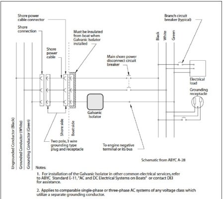
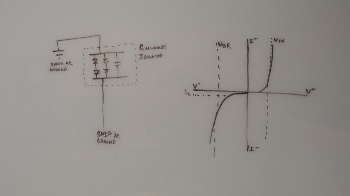
Regardless, back to our friend the galvanic isolator. I've attached a picture of what a basic galvanic isolator looks like in my mind. It includes two pairs of two diodes each. Each pair has two diodes in series and oriented the same way. The two pairs are wired in parallel, but in opposite orientations. The effect of this is that voltage in excess of ~1.4V (2* ~0.7V) in either direction will "switch on" the diode pair oriented in that direction, "closing" the diode just like "closing" a switch, allowing current to flow. But, voltages less than ~1.4V in either direction won't be sufficient to "Switch on" the diode pair, leaving the diodes "switched off" and leaving the ground path "open", just like an "open switch".

It also includes a capacitor, wired in parallel, because capacitors will pass AC but not DC (DC saturates them, so somewhat like a fully battery, they don't let more juice flow, whereas AC keeps reversing, so it just time shifts the current and voltage curves, but doesn't prevent current flow). So, the capacitor won't let DC stray current pass through, but can do two things. The first is provide a way to let AC current that leaks to ground on the boat, such as from surge supressors, leave the boat via the ground-- without saturating the diodes, switching them "on" and thereby letting DC stray current through with the AC leak current. The second is to provide a back-up path for AC to leave the boat if a diode fails and remains as an "open switch" even when it should "switch on" or "closed" to let fault AC out.

I've never tried to build my own galvanic isolator. I don't put science experiments on my boat. So, I've never thought about (a) if there should normally be enough leakage to make it worth the capacitor for that purpose (or if such leakage should simply be fixed). Nor have I thought about whether or not the diodes are likely enough to fail to need a capacitor as a back-up path. Nor have I thought about whether or not I could select a capacitor such that it could serve both purposes, or if I would need to pick one or the other. On my own boat, I installed an ELCI, so, although I've never measured, any AC leakage current on my boat must be somewhat low.

So, back to my question...my belief is that, with a voltage of less than ~1.4V the diodes are "switched off/open" and no current is flowing along the path, despite the potential and current course. And that voltages above ~1.4V "Switch the diode on/closed", allowing current to flow along the path. And that at least one purpose of a parallel capacitor is to prevent leaking a relatively small amount of leaking AC current from "Switching on" a diode pair (half the time) allowing DC current through, even thought eh DC current is below the ~1.4V threshhold.

Basically, I really do think the diodes operate as voltage-controlled switches.

What am I missing here?

Thanks!

-Greg
 

Attachments

  • 0505190148.jpg
    0505190148.jpg
    26.9 KB · Views: 28
Last edited:
I was just looking back over my post. Next day proofreading is always bad because that edit button disappears!

Let me correct this:

Just for completeness, what happens if one reverse biases a diode? Well, for a while, nothing at all. There are a bunch of free holes one one side that already has a bunch of free holes. And, there are a bunch of free electrons on a side that has a bunch of free electrons.

To read as this:

Just for completeness, what happens if one reverse biases a diode? Well, for a while, nothing at all. The reverse bias is the opposite of a forward bias and, instead of acting to collapse the depletion zone, it attracts more cross-over and causes it to grow, further resisting current flow.

(The bit about free holes supplied on the free hole side and free electrons supplied on the free electron side was accidentally copied from the forward bias paragraph while editing -- it is the forward bias situation, not the reverse bias situation, and increases the potential which collapses the depletion zone and facilitates current flow)

Cheers!
-Greg
 
Back
Top Bottom