Fusing batteries - Con-fusing!

The friendliest place on the web for anyone who enjoys boating.
If you have answers, please help by responding to the unanswered posts.

DHeckrotte

Guru
Joined
Nov 1, 2015
Messages
1,024
Location
USA
Vessel Name
Revel
Vessel Make
1984 Fu Hwa 39
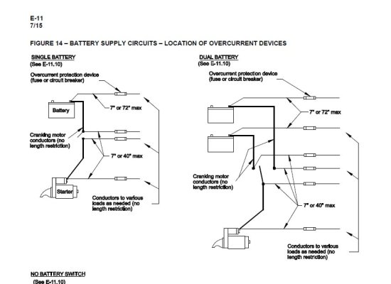
I've read all sorts of opinions about fusing batteries. ABYC requires fusing batteries for non-starting loads, but not on starting circuits (unless there's more lead on the boat than any of us have). Some folks recommend fusing all battery + wire at the battery. Some folks recommend fusing all battery + and - wire at the battery. Seems to me that I understand that fusing is sized to protect the wire. Even on house wiring, the fuses/breakers are sized to the circuit wire and not to the smaller stuff in devices and appliances. Battery wire is usually, it seems, way oversized for the loads despite the cost involved; presumably oversized for current losses in the cable.


Resultant questions: Fuse in accordance with ABYC? Fuse all battery + wire at the battery? Fuse all battery wire, + & -? Size fuses for the expected loads rather than oversized for the wire?


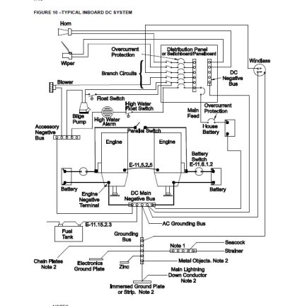
An inquiring mind wants to know: How come the seriously sized grounds (batt negatives) in the boat are not bonded to each other? Each engine is grounded by virtue of its own battery negative. The house side is similar in that the ground buss is connected to the house battery. The old/existing 110v battery charger connects all the battery negatives with a relatively small conductor. Blue Sea diagrams show an undefined 'ground' at each battery with the assumption that they are all 'ground'. Am I showing everybody why I failed 'Electricity and Magnetism' in first year Engineering?


I will be replacing all the 1/0 / 38 mm wire on the boat since I've found failed insulation on some of the 35 year old stuff. I'm adding ACRs and wiring battery switches correctly so that the engines will charge the house bank, will combine batts for low batt conditions, and isolate low batts. I will be adding at least the ABYC fusing.


And I ought to replace the wire to the anchor winch and add a breaker at a convenient place (rather than a switch at the head of the forward berth).
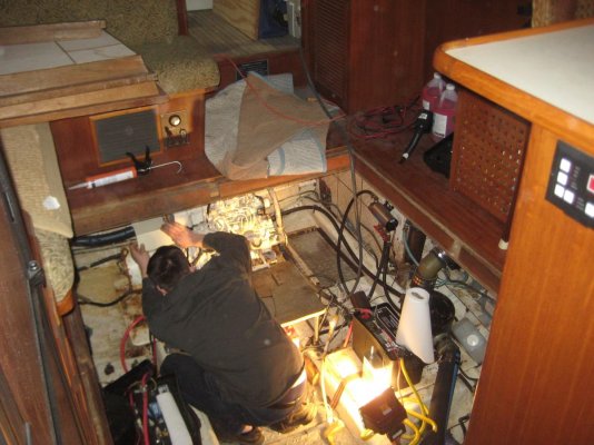
 
DH
First full disclosure... no marine electrician I'm a mechanical type but have dug into ABYC specs a bit.
AFAIK and my logic batty fuse protects main feed in case of a short. Really can't size for load as there are likely many... thats what the distribution panel and associated breakers are for.
Only dedicated battys... I suppose like a thruster couldbe fused for the connected load.
Never heard of fusing Neg and not sure what that accomplishes.
 
On twins the ground between each engine must be the same size as the (cranking) ground wire that goes to the batt... They are virtually the same potential as seen by the bonding system.


thus...


You only want 1 connection from the bonding system the engine(s), a single point reference to the boats ground which the CG picked the engine block as it since the engine is the closest point electrically to the sea.


fusing the cranking circuit adds risk of voltage drops while cranking cause of poor teminations and or corrosion. I add a 600A switch on the positive lead to the starter so I can isolate a batt or the engine itself. dont fuse the neg leads, ever.


" Fuse in accordance with ABYC" as they use the CG regs as a minimum and sometimes go beyond them.
 
Last edited:
While we are talking about battery cables... Was installing another cranking battery in the Mainship so I had to move the house batteries around a bit. Ground wire from the thruster came out of the crimped lug on the battery
Not sure of the size but it was 'something ought'... Big as my thumb. No way for me to crimp it or even get it back in the lug. No way with out a big hyd. crimper to fix.
I know ABYC says "mechanical fastening" but now I'm wondering about the rest of the connections....
All the wiring appears to have been re-done, and done well. Crimped and shrink tube over it. Maybe just a bad crimp....Or vibration worked it loose.

I'd much prefer crimped AND soldered connections...
 
Consider Blue Seas MRBF or Battery Terminal fuses. I have them on the battery leads that feed the battery switches for both house and start. They handle my Perkins 6.354 for 4 years now and Magnum 2000w inverter without a failure.
 
Last edited:
Consider Blue Seas MRBF or Battery Terminal fuses. I have them on the battery leads that feed the battery switches for both house and start. They handle my Perkins 6.354 for 4 years now and Magnum 2000w inverter without a failure.


I really like these. It puts the fuse right at the battery and is the easiest way to install a fuse. Just be away of the max amp rating on the fuse. A large engine starter could draw more amps than the largest fuse available.
 
https://www.grainger.com/product/EATON-BUSSMANN-4000A-Time-Delay-Fiberglass-6F525?cm_sp=Product_Details-_-Products_Based_on_Your_Search-_-IDPPLARECS&cm_vc=IDPPLARECS


Yes, you can buy a 4000 Amp fuse. :socool:
But, at over $2600 each, you might want to size it correctly in the first place!

Yes, please connect all "grounded" batt leads, and engine wires to a common point. Blue Seas makes some very nice NEG blocks for the purpose.
Never a need to fuse the NEG side on a battery IF the POS side is fused. The same is not true for the load end, in certain circumstances.
 
Minor, but expensive progress made. Sitting on the deacon's bench here at home are: new 40amp battery charger, 1/0 boat wire in black and red, adhesive-lined shrink tubing, terminals, MRBFs and fuses. The ACRs are on the boat. Now, all I have to do is install it all and find time to lure my slender tool-using son aboard to do (most of) it.


As for soldering crimp terminals, I used to think it a dandy idea but: it's hard to get the larger multi-stranded conductors hot enough w/o collateral damage, you have to convince yourself that you've done a good job w/no cold joints with higher resistance, you risk localized damage to conductors when they are flexed. Interestingly, house wiring in the good old days used to be soldered and taped. That is considered wrong today in favor of wire nuts and other mechanical connections. Soldering won't pass inspection, either.


I guess the varied ground potential is a non-issue. The boat has a bonding system (of questionable integrity after 34 years). And the current non-functional battery charger uses a daisy-chained relatively small (#10 awg?)
ground to the three banks.

Well done Doug!
I am in the same process and cannot wait to be done with all this!
Any picture of your new setup?

L
 
For service circuits # 4 wire and thinner soldering after using a "proper " crimp tool is easy.

The setup is to get a good sized roofing copper 3-5 lbs or so , heat it with a propane or map torch.

The massive hear carried by the roofing copper almost instantly heats a terminal to soldering temperature.

There is no stiffening from melting in tinned cables .

Smaller cables can be done in batches if rewiring an older boat.

Shrink tubing to protect the joint, burglar alarm wiring tear off pad numbers for circuit numbering , at terminal and a foot away covered with majic tape and copper star washers under hold down nut .Done !!!!

Boats undergo more modifications over the decades , but wiring that is done right almost is forever.
 
Resultant questions: Fuse in accordance with ABYC? Fuse all battery + wire at the battery? Fuse all battery wire, + & -? Size fuses for the expected loads rather than oversized for the wire?

-When sizing battery bank fusing it is there to protect the wire but the wire should be large enough for the fuses trip rating.

-Fuses should meet the AIC requirements based on bank size. Generally ANL, Class T or MRBF can do this but MRBF is limited to 300A and are really not optimal for starting larger trawler motors..

-The fuse is only required in the + and preferably within 7" of the battery bank. Under certain circumstances you can go to either 40" or 72" before fusing is required.

-I fuse all banks, if they can be.

-If the starter loads are too big to fuse then the battery cable between the starter and bank is enclosed in a durable protective sleeve or conduit not just "electrical tape" as is technically allowed as sheathing under the ABYC 40" or 72" rule exception..

-Any bank other than the cranking bank, that can be used for starting or other large loads, via emergency parallel or crossover switching, needs to have the wiring and over current protection to satisfy the largest on-board loads without nuisance tripping. In other words just because your house loads will never exceed 150A you would still need the battery cable infrastructure and fusing to satisfy the starter motor IF the bank can be switched to parallel, or used on its own with start isolated, to start the motor. I see this mistake, house fuse grossly undersized and connected to a parallel switch, all too frequently.

-The bare minimum fuse size I use for any engine starting, even for sailboat engines and generators, is 250A.

-If I had to guess I likely have 20,000 plus motor starts on fuse protected banks. In today's day and age there are only a few installations where it is not possible to protect with a Class T or large ANL and again, in that case I use a protective sleeve or conduit.

-Keep in mind that so long as a fuse does not nuisance trip any fuse, even if larger than the ABYC calls for, will be safer than no fuse at all. I suspect too many people lose sight of this.. In over current experiments for LiFeP04 batteries I've tripped 300A fuses using 15' of 8GA wire and the wire never even had a chance to get warm to the touch. These trips all instantly overloaded and maxed out the 1000A capabilities of a Fluke 376 clamp meters in-rush capture feature. I am not suggesting fusing at anywhere near this extreme, but again any fuse will be safer than none so long as it is not nuisance tripping. If that 300A fuse had not been there, to protect that 8AWG wire, even though under ABYC standards that wire is grossly under sized for the fuse, the wire would have literally burned off the jacket until the wire itself was a glowing red fire starter....
 
Last edited:
I try to apply a bit of common sense to the ABYC code.
I've installed and easily accessible ANL fuse for the house battery bank just as the cable comes out of the enclosed battery box. The two feet of un-fused cable is way oversized and protected from damage.
I did the same with my windlass cable. Then I ran slightly oversized cable to a windlass circuit breaker at the helm. It may not be 100% compliant but I'm ok with that.
 
Never heard of fusing Neg and not sure what that accomplishes.


Does exactly the same thing as + fusing. If the fuse blows and the current can't get back to the battery, it's out of the circuit. I did it on my sailboat on the advice of an ABYC surveyor and well known Internet boat systems expert who said it is very common in Europe. Plus fusing would have been complex on that boat because of the battery / battery monitor configuration. The fuse in the single black cable running back to the battery bank made it simple.
 
Ground wire from the thruster came out of the crimped lug on the battery
Not sure of the size but it was 'something ought'... Big as my thumb. No way for me to crimp it or even get it back in the lug. No way with out a big hyd. crimper to fix.


Whomever installed that terminal used improper crimp tooling & practices. Please don't judge crimped terminals by someone who did a poor job or tried to cheat the system and purchased a substandard tool.

The crimp tooling we use on customers boats would require approx 1000 pounds of pull force to extract a 2/0 lug from the 2/0 wire. I know this because our crimp tools are tested to ensure the tooling is not drifting out of spec.. Pulling a thumb diameter wire out by hand does not even meet Tonka-Truck or Lego reliability levels.;) It certainly warrants that every lug termination on-board be inspected. Scary stuff for sure..
 
Does exactly the same thing as + fusing. If the fuse blows and the current can't get back to the battery, it's out of the circuit. I did it on my sailboat on the advice of an ABYC surveyor and well known Internet boat systems expert who said it is very common in Europe. Plus fusing would have been complex on that boat because of the battery / battery monitor configuration. The fuse in the single black cable running back to the battery bank made it simple.
My thinking re Neg fusing is that if the wire shorts at any place in the circuit it won't blow a Neg fuse it will overload the wiring. The Neg only blows if the circuit is intact and overloaded.
If the Pos is fused and the circuit shorts it blows.

What am I missing or not considering.?

CMS... any expert comments?
 
Does exactly the same thing as + fusing. If the fuse blows and the current can't get back to the battery, it's out of the circuit. I did it on my sailboat on the advice of an ABYC surveyor and well known Internet boat systems expert who said it is very common in Europe. Plus fusing would have been complex on that boat because of the battery / battery monitor configuration. The fuse in the single black cable running back to the battery bank made it simple.

NEG side fusing has an advantage in that inadvertent shorts from a exposed fuse/fuseholder to engine block or other grounded object do not make sparks.
 
Yes, follow ABYC standards for over-current protection. Can you think of a reason not to?

The notion behind not fusing the start cable is, in the case of a weak battery the current will rise, which could cause nuisance tripping of fuses, which could in turn create a safety hazard if you can't start the engine in an emergency. For that reason, the start positive cable does not need to be fused (it can be), however, must be very well-protected/sheathed and carefully routed, and it is not allowed to touch the engine block in any way.

With the exception of motor loads, you are correct, over-current protection is designed to protect the wire and not the device/appliance, and wire size is driven by its ability to carry current (which is also driven by insulation temperature rating), while meeting maximum voltage drop needs, 3% or 10% depending on what's being powered. This all can be confusing, which is why it makes good sense to use one of the wire size apps or websites such as the one from Blue Sea Circuit Wizard - Blue Sea Systems

I would post the diagrams relating tho this issue here, however, it seems I can't post photos unless it's a url. Alternatively I've just posted them on my Facebook page, here https://www.facebook.com/stevedmarineconsulting

This brief article covers the subject of over-current protection https://www.proboat.com/2016/12/circuit-training-improving-overcurrent-protection/
 
I try to apply a bit of common sense to the ABYC code.
I've installed and easily accessible ANL fuse for the house battery bank just as the cable comes out of the enclosed battery box. The two feet of un-fused cable is way oversized and protected from damage.
I did the same with my windlass cable. Then I ran slightly oversized cable to a windlass circuit breaker at the helm. It may not be 100% compliant but I'm ok with that.

If the un-fused/un-protected cable length, i.e. the portion between the battery and fuse, is less than 7", it's compliant. That's a tall order in many instances, so there is an exception, if the wire originates at a battery, the length of un-fused/un-protected cable can be extended to 72" provided it's supplementally sheathed, which means in a conduit, in ABYC compliant wiring loom, or even wrapped in electrical tape, although I would not recommend the latter.

When I ran a boat yard I routinely reminded my electricians to keep the unprotected wire length as short as possible, just because you have 72" doesn't mean you should use it. These distances are slightly different if the wire originates at a battery switch or starter post, these are shown in the diagrams I just posted here https://www.facebook.com/stevedmarineconsulting
 
My thinking re Neg fusing is that if the wire shorts at any place in the circuit it won't blow a Neg fuse it will overload the wiring. The Neg only blows if the circuit is intact and overloaded.
If the Pos is fused and the circuit shorts it blows.

What am I missing or not considering.?

CMS... any expert comments?

You aren't missing anything, you are correct.

"ABYC E-11.10.1.1.2 Overcurrent Protection Device Location - Ungrounded conductors shall be provided with overcurrent protection within a distance of seven inches (178 mm) of the point at which the conductor is connected to the source of power measured along the conductor (see FIGURE 14)."

While it's true current flow on the negative side of a circuit is equal to that on the positive side, and thus it could in theory be fused, doing so is frowned upon to say the least in the marine electrical world with good reason.

Over-current protection, as well as switches, should be placed on the un-grounded, i.e. positive side of a circuit. Failing to do so means that if a positive cable comes into contact with any grounded or bonded object, one which isn't part of its own immediate circuit, an engine block, fuel tank, seacock etc, there is no protection because the ground/bond to these devices is not fused and doing so is prohibited, fuses cannot be installed in normally non-current carrying conductors such as bonding, grounding circuits because, among other things, if the fuse blew you'd have no way of knowing it, and it then presents an electrocution hazard for AC circuits whose hot conductor inadvertently makes contact with a grounded object, whose fuse has blown.

If the positive and negative cables of a circuit, one where the negative is fused, short to each other, the fuse would blow, but that's often not the way short circuits occur.
 
I've been enlightened regarding image insertion by another member, thanks.
 

Attachments

  • Grounding ABYC.jpg
    Grounding ABYC.jpg
    102.3 KB · Views: 67
  • Over Current Protection ABYC.jpg
    Over Current Protection ABYC.jpg
    85.7 KB · Views: 59
Steve:


You have opened yourself for dozens of comments about your diagram. Mine is that bilge pumps and high water alarms should be supplied directly from the batteries and not through the DC panel where you can easily forget and leave the breaker off.


David
 
Steve:


You have opened yourself for dozens of comments about your diagram. Mine is that bilge pumps and high water alarms should be supplied directly from the batteries and not through the DC panel where you can easily forget and leave the breaker off.


David
Agree... partially.... they need protection and shouldn't be ob a batty sw or main breaker. My MS has a second distribution panel that is split and half bypasses the batty sw and feeds those devices that should remain live. Those breakers ( don't know the correct nomenclature) have no toggle but can be switched off using a small flat blade screw driver or back on w a simple push of the exposed side of a rocker sw.
 
Agree that there should be an instantly verifiable/accessible switch and breakers for otherwise unswitched battery loads. Our boat was wired with a bilge pump breaker downstream from the battery switch in the main panel. It's been taken out of the circuit and I've got to find out if/where it's now fused. There are (in true PO mode,) a couple other circuits wired from the panel area which are similarly live.


I'm sure a good many folks simply leave their 12v panel 'live' for the season; I'm used to leaving everything 'off' that I can. However, I've fallen into leaving one of the 110v panels live (for battery charger and refrigerator) (separate, later panel for AC).
 
I'll post this thought and quickly run down to the basement, to continue work restoring an 1840's melodeon (tiny, folding pump organ), so as to be out of range of slings and arrows.


I'm using the Blue Sea diagram for three banks, three battery switches and two of their ACRs. As they drew it, it seems as though the ACRs would be closer to the battery switches and house panel.


As the boat is, it seems as though the ACRs would be happier and have shorter wire runs if they were closer to the three battery banks. They say, but I don't know why, that the ACRs should not be too near the batteries; perhaps they're worried about a battery acid off-gassing acid and corroding the relays.


So, here goes: The engine start batteries are on the same shelf on the stringers as the fiberglass water-lift mufflers. 2 or 3 inches between them. Batteries are in plastic boxes. House bank is between the start batteries but about 2' further aft. There's no handy place to install the ACRs that also is not adjacent to water system hoses, pump, heater and tanks. I've got to repair one of the fiberglass mufflers for leaks at the glassed-on connections, so I'll have epoxy and 'glass in hand. Seems to me that it would be perfectly structurally sufficient to bond onto each muffler a 'glass bracket to carry each ACR. Relatively cool. Distant from water spraying from failed hoses (never happens...not). Close but not too close(?) to the batteries.


Pic shows the two engine start batts and the two mufflers. The house bank is under the plywood panel behind, aft, of my son as he works on the genset.
 

Attachments

  • 2016-02-24 Nuri_Genset 003.jpg
    2016-02-24 Nuri_Genset 003.jpg
    137.5 KB · Views: 42
Last edited:
"Mine is that bilge pumps and high water alarms should be supplied directly from the batteries and not through the DC panel where you can easily forget and leave the breaker off."

This is called a Hot Battery Bus ,it is normally on even when all else is shut down , and circuits are individually protected by fuses.
 
Steve:


You have opened yourself for dozens of comments about your diagram. Mine is that bilge pumps and high water alarms should be supplied directly from the batteries and not through the DC panel where you can easily forget and leave the breaker off.


David

David, I'd agree that bilge pumps need to be on what's called a "live" or "24 hour" bus, however, that doesn't mean it can't be energized from the panel, no need to power directly from the battery per se. Pump and alarm breakers can be supplied from the line side of the main breaker, so shutting that main breaker does not kill power to them. The ABYC diagram does not show that, however, there is no specific ABYC requirement for it, which is why it's not included. If you want to be able to **** off the house battery switch and have this gear still work, and you should, then you'd need a home run back to the line side of that switch or to the batteries directly. Furthermore, those critical breakers should be protected using a cover like this https://www.bluesea.com/products/4100/A-Series_Circuit_Breaker_Toggle_Guard

As an aside, most electronically-controlled diesel engine manufacturers call for power to be connected directly to the battery (in the case of the engine its ECU), and they mean it, they should not be connected to power supplies at the panel, battery switches etc. They must be over-current protected of course, my preference is for circuit breakers rather than fuses for these critical items, in troubleshooting a fault you may go through your entire supply of fuses without identifying the problem.

I routinely tell folks in the industry with whom I work, ABYC Standards are a minimum, they are the floor not the ceiling. Here's an example, the Standards say that batteries, once installed, can move up to an inch. In my opinion that's preposterous, under what circumstances would it be desirable to have a battery move? Batteries should be entirely immobilized.

On the subject of soldering, solder is prohibited for use by ABYC, outside electronic enclosures, radios, radar etc, as the sole means of connection. There is an exception for battery lugs designed to be soldered, but those are rare these days. The reason for this rule is an overheating circuit may melt the solder, releasing the wire, causing a short. You could solder after making the crimp, however, I don't believe it makes any difference provided a good quality solderless terminal us used, and it's properly compressed. If crimping alone is good enough for Boeing it's good enough for the marine industry. The subject is covered in detail in this article Crimping Etiquette | Steve D'Antonio Marine Consulting
 
Back
Top Bottom