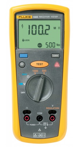
This you can definitely do yourself if you have a multimeter. If you don't, get a cheap one online and play with it a bit. Watch a few online videos. You don't need to become an expert on this stuff, but it feels good to at least be able to find out when a wire is energized or not, whether something is shorted to ground, etc.
Set the meter on the OHMS setting...this is a continuity test, or a test to determine if one wire is connected to another. Touch the two test probes together and see how the reading goes to zero...this means zero resistance in the circuit...total continuity between one probe and another.
So you coil up the cable, both ends unplugged. Insert one probe (doesn't matter which) into one of the connections, making sure that it's in contact with the metal inside. Do the same with the other probe in each of the other connections AT THE SAME END of the cable. The resistance should be infinity, i.e., there should be no continuity between any two of the wires in your cable. Repeat this so that you check all the combinations of conductors in your cable (whether 3 or 4). If at any time the reading between two of the connections goes to zero, as it does when you touch the probes together, that means a "dead short" exists between those two wires in your cable.
Much more likely, however, would be some partial electrical leakage between two wires, in other words, some resistance value other than infinity and zero. Oftentimes it takes some flexing of the cable to reveal this.
Then check continuity along each wire within the cable by inserting the probe into the same wire's connector at both ends of the cable; the resistance should be zero.
If this were my boat, I'd focus on the items that the second outfit identified and go from there. Unless your shore power cable is quite old and worn out, it's the least-likely source of any problems. Please note that I am NOT an electrician.
Thanks for sharing your experience with us!
")