Delfin
Grand Vizier
- Joined
- Jan 20, 2010
- Messages
- 3,822
Better to just use cell "balancing", IMO calling it equalization may confuse some.
And let go of the voltage/SoC idea, not applicable in this case.
When float is set lower than actual, then that should functionally be the same as Off, no current flow into the battery, but any loads carried by the charge source. Only extremely high-amp loads should cause any voltage drop.
Also, there is no "ideal SoC" except for when not cycling, which is way down near the bottom of what the BMS allows. While cycling you will go between "full" and "empty" as defined by the BMS, passing through 60% twice each cycle.
Do you know if your BMS initiates a new bulk/absorb charge cycle based on SoC via coulomb-counting?
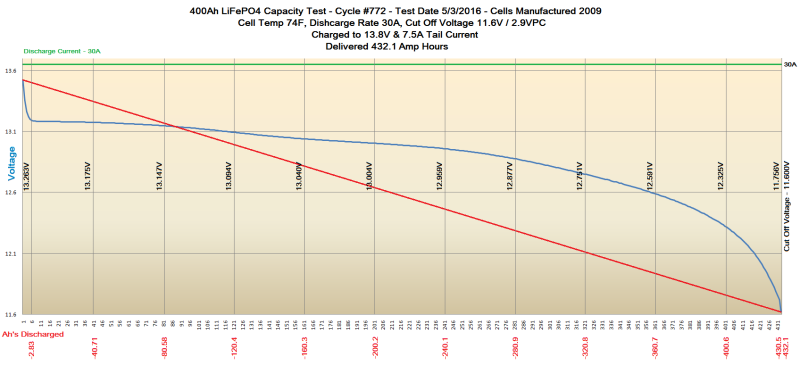
While Li battery voltage doesn't taper like LA batteries, it does taper, so I'm not sure it is correct to say that voltage/SoC is not applicable. Just different, as the manufacturer says.
And no, the BMS doesn't have any impact on the behavior of the charging sources. It just sits between the battery and the load and is best thought of as part of the battery. All it can do to the charging source is disconnect while allowing the load to continue to draw if it is a two channel, or disconnect both charging source and loads if a single channel.