Different ways to wire multiple batteries

The friendliest place on the web for anyone who enjoys boating.
If you have answers, please help by responding to the unanswered posts.
I believe in trying to do things the best way possible. I also realize that some times the best way for one part of the boat can compromise another part of the boat. Would be nice to set up bus bars and have equal distance cables to all batteries but not if this created a trip hazards. Then all the hard work of perfect cabling can be meaning less if you allow one battery cable to suffer more corrosion than the others.

Sometimes it’s had to know were real value is.
 
Most multibank battery chargers share their output across isolator diodes for each bank they charge. If the load on one bank is less than on another, likely the charger output is going to slightly overcharge the more lightly discharged bank, because the charger has to charge all the banks together off a single circuit creating power from 120vac, that same output being shared among all banks.

Maybe very very expensive chargers can adjust each bank independently, but most cant. Be like having a separate charger for every battery bank.

It is why my two 12v batteries on the house bank read 13.8 and the single starter battery on the starter bank can read 14.4, when the house batteries are discharged. And it also seems true that when both banks are charged just having 2 batteries on one bank and 1 battery on another creates an uneven load and an uneven voltage of a few tenths of a volt.

So balancing banks equally with same numbers, type, size and also condition of batteries in each bank might help equalize the voltage output to all banks from the charger, but it has not affected my single start batteries ability to crank up the engines one bit, or lifespan that I can tell not doing so.

So all these schemes of wiring I dont think make any difference. Having different numbers of batteries in various banks affects the voltage much more than that does. And for the last few years has had no affect on my batteries that I can tell.
 
Last edited:
Inverter/chargers would not operate with inline diodes blocking flow both ways, IMO

They would if they have a way of switching that charge part of the circuit on and off, like a relay.

there is a charge mode and then a separate inverter mode.
And it can be done in silicone so would appear as a seamless transition to you or something plugged in.
 
Last edited:
Thanks!


We seem to debate the minute details of things here on TF. I am not sure why, but I suspect that people are trying to do things that they are unfamiliar with, so they google the issue.


I think that is Wonderful, but we always need to remind ourselves that there a lot of different and very valid ways to do things, and that the difference between “good” and “perfect” is often immeasurable in practical applications.


Agreed. However, I have learned a lot by reading TF members debating minutiae about subjects that I’m not well versed in. I also tend to be a bit geeky so that kind of stuff interests me.
 
I think we can all agree that regardless of which wiring method the system works for a period of time before recharging.
I further think that the only reason to consider wiring options is to extend the time the system works before that recharge is necessary.
For those where the simplest wiring lasts long enough before it needs recharging this thread topic will be boring.
 
Hi powder ??? if i run a solor on my boat should i go with 12 V inverter or is it best to go with 24V system . and 6V battery's or 12V battery's . i will be running a small refrigerator, TV , and 3.5 freezer , thanks BR
 
I agree with Kevin on the veracity of taking supreme effort to keep wire distances, etc near perfect.

But, I do believe in having a place to plant each large wire on a BUSS, to avoid multiple connections on a particular battery. Not to do with "balancing", but to do with battery removal ease. It gives me the shakes to see more than two wires going to any battery post. It is best to provide an easy way to remove just one battery and not take out any more.
 
I would argue that with the close proximity of batteries to one another and the use of adequate sized cable that there are really no measurable losses across the wire, and therefore no real differences between wiring techniques.

I read the linked article by the OP, and it says you are wrong. Just sayin'. :)
 
uneven charging

I had a situation where one of my 12 volt batteries in a multiple hook up, although all purchased at the same time, presented the voltage regulator with the message that it was fully charged and meanwhile the other batteries just ran down further and further, the only way I could charge them was to disconnect the good one. The only way I could get over this was to go to 6 volt golf cart batteries in series and have 2 banks which I alternated to get the charged. I ultimately installed solar and had 2 systems , one for each bank with separate controller/regulators ,this worked a treat.
 
At this point.........
I bought a new anchor......
Just sayin’.
 
Multiple batteries connected to a single charger is a bad recipe, period. If you have 3 batteries you need 3 chargers or a charger built for 3 batteries. (ie: the charger has 3 outputs)
 
Why is it a bad idea? Blue Sea makes some very well received charging relays that far surpass the old battery isolator technology.
 
I’ll submit parallel charging is a bad technique if they are of different chemistries. Or, if there is a weak cell in the mix; especially a shorted cell. Beyond that, should be ok. I have even argued that differing sizes is ok in parallel; again with the above restrictions.
 
I’ll submit parallel charging is a bad technique if they are of different chemistries. Or, if there is a weak cell in the mix; especially a shorted cell. Beyond that, should be ok. I have even argued that differing sizes is ok in parallel; again with the above restrictions.


I agree that the charging relays work great if the charge profiles for the different battery banks are the same. If they are different, it isn't ideal.


For those of us that use our boats on the hook some of the time, or who aren't running a genset much of the time, I really like directing all the charging sources to the house bank which is most likely to be discharged the deepest, is usually the largest bank, and often the most expensive. This helps ensure that it gets fully recharged more frequently. Then the other battery systems can share that. If they are all the same chemistry, then a charging relay would fine. Otherwise, a DC to DC charger works really well. I have used two different types, but there are some nifty new extra special DC - DC chargers available which allow you even more customization. Of course they are also more expensive.


CMS's website has some good information.


https://marinehowto.com/understanding-the-sterling-power-pro-batt-ultra-battery-to-battery-charger/
 
Multiple batteries connected to a single charger is a bad recipe, period. If you have 3 batteries you need 3 chargers or a charger built for 3 batteries. (ie: the charger has 3 outputs)


Sorry I disagree, is each battery in a solar farm wired individuality?


Or if didn't a charger and used your alternator would need one for each.
 
Why is it a bad idea? Blue Sea makes some very well received charging relays that far surpass the old battery isolator technology.

I’m not familiar with the ‘relays’ you mention: do they include detection of shorted cells, battery temperature monitoring, isolation of batts with those or other problems, and fault display? Do they provide automatic ‘conditioning’ and other charging modes?
These and more are provided by modern, multi-battery chargers. I’m away from my boat more than on her and take comfort that a smart charger is monitoring and maintaining the batteries (2 ea 8D & 1 grp 27) and keeping her safe.
 
I’m not familiar with the ‘relays’ you mention: do they include detection of shorted cells, battery temperature monitoring, isolation of batts with those or other problems, and fault display? Do they provide automatic ‘conditioning’ and other charging modes?

These and more are provided by modern, multi-battery chargers. I’m away from my boat more than on her and take comfort that a smart charger is monitoring and maintaining the batteries (2 ea 8D & 1 grp 27) and keeping her safe.


Sure, if you have two bank having a smart charger than can give you two independent charging profiles is nice.

So, you have 3 batteries. I assume that your GRP 27 is a starting battery. Genset? What do your two 8Ds do?
 
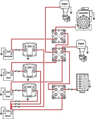
Blue Sea Automatic Charging Relay (ACR). Upgraded version of the old isolation transformer.

https://www.bluesea.com/products/76...rging_Relay_with_Manual_Control_-_12V_DC_500A

It is solely a switch. If you want monitoring and readouts, look at the Blue Sea M2 meters. I use a state of charge (SoC) meter for 12v system monitoring, though I can also pull battery and alternator temp off other devices if desired (solar MPPT controller, magnum charge/inverter).

Wiring diagram off Blue Sea website for a complex ACR installation. They have other diagrams for less complex config 2015-4batt_2eng_1gen.jpeg
 
Sure, if you have two bank having a smart charger than can give you two independent charging profiles is nice.

So, you have 3 batteries. I assume that your GRP 27 is a starting battery. Genset? What do your two 8Ds do?

Correct re: GenSet starting batt, which that batt is dedicated to exclusively. The 8D’s are starting & house (single diesel Mainship 350). One thing I consider important is to not leave the 8D switch in ‘ALL’ when on shore power as this puts the 8Ds in parallel effectively negating the 2 seperate charging ‘channels’.
 
So what do you recommend for an inverter/charger charging a 1000+/- amp hr bank?
 
So what do you recommend for an inverter/charger charging a 1000+/- amp hr bank?

I don’t claim that degree of expertise! I recently had to replace a failed charger so researched heavily before buying.
Charger manufacturers usually recommend a charger output based on the A/H of the battery. Advisors tended to prefer lower charger output levels than manufacturers. (Eg: mfrs recommended 60 amp, I originally had 20 amp; I purchased a 40 amp model + a remote panel) I also added a 50 amp fuse in each of the charger outputs, as recommended.


That's why you are getting pushback on single source charging for battery banks with batteries in parallel.


It's not practical in all cases to charge pairs or singles in multi bank battery banks.


While there is "best" ...it ain't always possible or practical.
 
1000AH battery bank is pretty big. This is part of my refit so I can tell you what I have done, but not a recommendation for anyone else.

I went with a Magnum 3012M Hybrid Inverter. 3000W power, overpower protection, and the hybrid technology means you can gang-together power sources (Solar + Shore Power, for example). I chose Magnum over Victron for two reasons: (1) the Magnum controllers are more analogue vs Victron is Bluetooth - I have just had too many issues with network/integrations, so am banning IP Addresses from my boat to the extent possible. (2) Auto-Gen-Start. Magnum integrates well with my NL generator, whereas Victron requires some sort of intermediary box.

To be fair, Victron has a fine reputation - my MPPT Solar Controller is Victron, but I just prefer the more hard-wired interface for Magnum in this application. Display is not nearly as fancy looking, but is bulletproof. Just not a place I want extra technology.
 
Didn't some Magnum dealer here just blast magnum inverters for catching fire...maybe just some years/models?
 
So what do you recommend for an inverter/charger charging a 1000+/- amp hr bank?

I don’t claim that degree of expertise! I recently had to replace a failed charger so researched heavily before buying.
Charger manufacturers usually recommend a charger output based on the A/H of the battery. Advisors tended to prefer lower charger output levels than manufacturers. (Eg: mfrs recommended 60 amp, I originally had 20 amp; I purchased a 40 amp model + a remote panel) I also added a 50 amp fuse in each of the charger outputs, as recommended.

I think you already know the answer :blush:

A 1000 amp hour battery bank should be charged with the largest charger you can buy.

Thats because that you are never going to realistically apply too much charge current to a 1000 amp hour bank using commercially available marine chargers.

C&D (a huge manufacturer of commercial lead acid batteries) for example recommends limiting initial charge current to C/2 where C is the capacity in amp hours at the 20 hour rate. No way to get there since the largest charger I’ve ever seen on a recreational boat was 150 amps.

People flat out do not understand batteries, and charging, and how to size a system so that all the components work together.

In order to be somewhat optimized you need to look at battery bank size AND your ability to recharge that battery bank during a “reasonable” cruising time or generator run time, based on real life cruising styles.

What I see in many instances is too big of battery banks for the recharge capability, meaning that you are just wasting battery size, weight, and cost.
 
Last edited:
Most multibank battery chargers share their output across isolator diodes for each bank they charge.


Bingo!


It is sad that folks think and believe there is more smoke and mirrors going on than there really is.

Simplifying a bit here but....

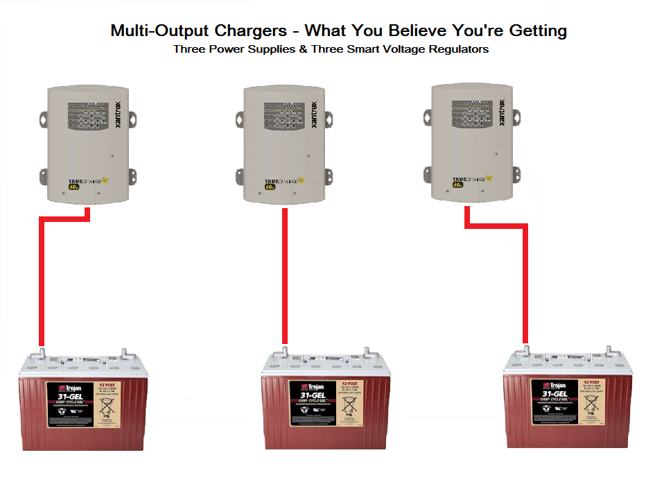
ACR-Multi-Output-Chargers.png


ACR-Multi-Output-Chargers-4.png


ACR-Multi-Output-Simplified-2.png


There are very few true multi-output, multi power supply and multi-voltage regulation chargers in existence. The vast majority of smart charger are use FET or diode isolated outputs all fed from one voltage regulated source.
 
Correct re: GenSet starting batt, which that batt is dedicated to exclusively. The 8D’s are starting & house (single diesel Mainship 350). One thing I consider important is to not leave the 8D switch in ‘ALL’ when on shore power as this puts the 8Ds in parallel effectively negating the 2 seperate charging ‘channels’.


So in your situation, I would probably first not choose to use an 8D for a starting battery (I've got an 8D for a starting battery myself and ain't gonna move it until I have to). I would send all charging sources to my house battery, shore charger, alternator, and any solar. I would then use an ACR to combine the house and the engine start battery when the house battery is seeing a charge voltage. For the genset, I would use probably use something inexpensive such as an echo charger which would keep the genset battery topped up. Again, the Echo charger would take charge current from the house bank when the house bank is getting charged.


The advantage to this is that all your charging current is going to the battery that needs it the most, the house bank. In the mean time, your start engines which would rarely be discharged very much, get topped off. This happens regardless of the charge source.


Separate chargers for separate batteries, or a charger with 3 outputs, is fine if you always have access to shore power. For boats that are off grid more often, it would not be my first choice.
 
People flat out do not understand batteries, and charging, and how to size a system so that all the components work together.

In order to be somewhat optimized you need to look at battery bank size AND your ability to recharge that battery bank during a “reasonable” cruising time or generator run time, based on real life cruising styles.

What I see in many instances is too big of battery banks for the recharge capability, meaning that you are just wasting battery size, weight, and cost.


I agree Kevin. I emphatically agree that I don't understand batteries and charging!


My newish battery bank was nominally 780Ah when new. The manufacturer recommends a charge current of 20% of the C20 capacity during bulk charging. That would be 156amps. My charger will only put out 125amps. So I'm not hitting the max charge current that my battery bank could absorb and my bank isn't that large, and my batteries don't accept a charge as fast as other batteries.


Lifeline says they can be charged at 5C, or 5 times their 20 hour capacity during bulk charging. My charger can't hit that for just one Lifeline 8D battery.
 
What I can never understand is why a 110 volt battery charger is necessary for starting batteries. The starting batteries get charged by the alternator as soon as the engine or generator starts.

When the engine and generator are off, why would the starting batteries need charging?

Cars don't require battery charging at rest.

My one start battery bank starts the engine and generator, powers the thruster and windlass and has no dedicated 110v charger. I can combine the start and house battery if the start battery needed stopping up. My start bank are two G31's. I've never not been able to start in 19 years.

I do have separate house and start alternators on the Lehman.
 

Latest posts

Back
Top Bottom