d/c ground, A/C neutral and A/C green

The friendliest place on the web for anyone who enjoys boating.
If you have answers, please help by responding to the unanswered posts.

Talonewo

Senior Member
Joined
Sep 29, 2012
Messages
113
Location
USA
Vessel Name
Shintullah
Vessel Make
55' 1978 Defever
What is the relationship between the three?

I think D/C ground and A/C green can be connected after the isolation transformer??

Can green and neutral ever be connected? If so what would happen?
 
One more thing. .. I have a steel boat.. does that change anything?
 
There is also a green bonding wire ... for a complete picture add it to the mix of all possible interconnections. Can't wait to see the answers ... :dance:
 
Look up:
Charlie Wing's book Boatowners illustrated Electrical Handbook .
Nigel Calders Electrical and Mechanical book.
Study them.
There are others.

Get a proper marine electrician involved.

What other equipment are you working with or installing? Generator, inverter. They all have their requirements.

I think people will be reluctant to offer much advice about your questions. It is difficult to offer good advice for this subject over the internet. Too many possibilities of error from a simple misunderstanding. Too many variables from a distance to attempt.

A steel boat does complicate things. Serious damage can occur or someone can be seriously injured or killed if an error occurs.
 
One more thing. .. I have a steel boat.. does that change anything?

YOU BET!

That is why the knowledgable PO installed the isolation transformer .

Just use the schematic from the transformer mfg.
 
DC ground would be the negative wire returning to the negative post on a battery, or the common DC grounding point.

AC green is the wire that bonds the case of a device to the earth side of the AC electrical system. It is the non current carrying conductor to earth. If a device develops an AC short or fault, and the device case gets electrified, the green bonding wire gives that fault or short, a path back to earth. If the green bonding wire were not attached to the case or correctly attached to earth, with the cased electrified due to a fault, a person could get electrocuted if one were to touch the case as they would now become the path to ground

Connecting the AC green and the AC neutral can cause the AC green to get electrified if you had a reverse polarity situation.

AC neutral is the current carry wire that returns current to earth ( the white wire on a an AC system). Technically, the AC neutral is the ground wire on the AC system. AC neutral and AC green wire do not get connected while on board a boat, and are only connected/bonded together on shore if your only dealing with a shore power system.

I was schooled that AC green and DC negative be connected at one point and only one point on the hull. If you have multiple connections to ground on a hull you develop different levels of potential which can lead to electrolysis issues especially on the DC side.

Cheers,

Conall
 
Last edited:
Look up:
Charlie Wing's book Boatowners illustrated Electrical Handbook .
Nigel Calders Electrical and Mechanical book.
Study them.
There are others.

Get a proper marine electrician involved.

What other equipment are you working with or installing? Generator, inverter. They all have their requirements.

I think people will be reluctant to offer much advice about your questions. It is difficult to offer good advice for this subject over the internet. Too many possibilities of error from a simple misunderstanding. Too many variables from a distance to attempt.

A steel boat does complicate things. Serious damage can occur or someone can be seriously injured or killed if an error occurs.

This is a pretty good piece of advice.... particularly what I marked in red.

Usually I hate the posts that always say your an idiot for asking, if you have to ask you need more help than advice......

I would love to try to explain it all...but see the above...

There are so many different ways of wiring a boat in or out of "absolute ABYC" compliance or "suggestion"....that trying to do it post by post gets more and more confusing...not only to you...but to many that probably DO know what they are doing...have seen it a lot in forums.

Better to read up on it...get familiar with the big picture...then ask specifics that are bite sized and a little more clear to explain and understand.

 
What is the relationship between the three?

I think D/C ground and A/C green can be connected after the isolation transformer?? Yes

Can green and neutral ever be connected? If so what would happen?
Only at a power source such as internal to the Genset and Inverter (with a couple RARE exceptions depending on your entire wiring scheme), otherwise never on the boat side of shore power. If done you may be returning all your "power" back to ground through the water instead of the shore power cord.


So not to be one of "those guys" totally and being only somewhat completely serious here....see above in Blue

Seriously, read at LEAST a chapter in one or more books explaining it and several well written articles on the internet explaining the full concept...you have to see it as a whole before you can start to safely piece meal it (at least to a point....as any knuckle head can buy a piece of gear and wire it up according to instructions...as long as you can follow those instructions carefully and understand at least that chunk of electricity)...see...it get complicated already...:D
 
The proper protection of steel boats is well known but probably not by many here. Find a yard electrician who spends a lot of time on steel hulls.
Since you are in Texas the TX and LA commercial ship yards are where I would start.
 
To answer all of your comments.... yes, yes and yes. My story in a nut shell, I live in San Antonio and the boat is in Slidell La, just north of New Orleans. I bought it two years ago and have been making the 8 hour drive on weekends to work on it getting it ready for the trip to Texas. It has been on the hard for the past two years while the yard has been working on the exterior paint and fixing the damaged mast. The yard did not have shore power available where the boat was blocked. I knew as soon as it was in the water I would be able to apply shore power, but before I did that I hired an ABYC certified electrician to come look at the boat. The A/C electrical system is different, see attached photo. He was a nice knowledgeable guy but the system was too different for him and he could not figure it out(see my "what is a SHINASA post, he could not figure out what it is either) so his recommendation was to start over, his estimate was $10,000 in design fees alone. The boat had a compete refit in the early 90s, so yes the wiring is old but at that point we did not know if it was broken, why fix it if it is not broken.... I want a safe boat but I don't have an open check book and I can't see replacing something if it is safe and works.

As for reading books, yes I have been reading MOTORBOAT ELECTRICAL and electronics manual by John Payne but I did not have it with me on the boat the day I made this original post.

With a bit of time... chasing wires, reading books I was able to figure the system out... currently she is plugged into shore power and working great. For those who want the long story of how it works read on.

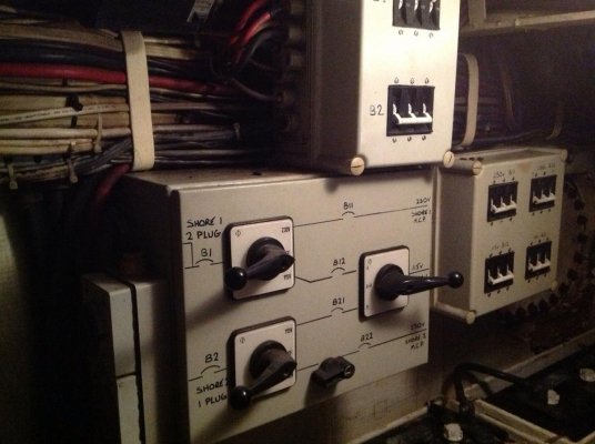
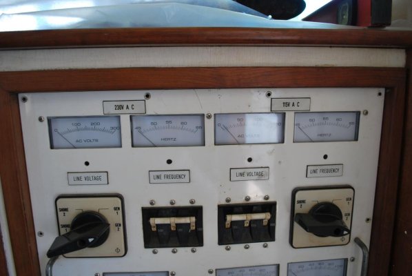
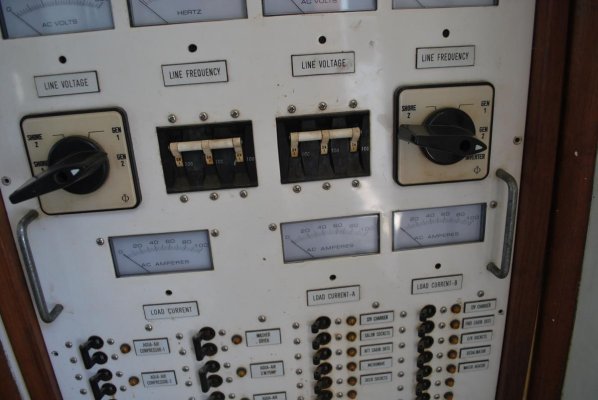
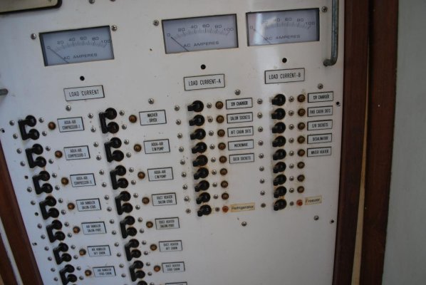
The boat has two 125/250 50 amp plugs... as soon as the wires enter the boat they are combined(red to red, black to black, white to white and green to green) and go into a 100 amp breaker labeled B1(just out side of the attached picture) the output of the B1 breaker feeds two things... first it feeds the B1 lever on the upper left of the junction or selector box, where you can select "230", "off", or "115".... the out put of the B1 breaker also goes to the mystery SHINASA box... the two load wires(red and black) go into the box and then output of the SHINASA box(two wires) goes to the input of the 100 amp B2 breaker in the photo..... but when they come back from the SHINASA they are connected to the B2 breaker as LOAD and NEUTRAL(or the white wire) and there is a jumper from the "load" wire to the other "load" pole of the three pole breaker... then the output of the B2 breaker goes to the lower 230 off or 115 selector.... so my assumption is the mystery box changes the phase of two load wire so I have a single full 50 amp 115 wire... from there the output of the selector box goes to the four 100 amp breakers you see in the photo from there it goes to the A/C distribution panel. The A/C distribution panel has a 230 side and two completely separate 115 legs you can see them labeled a A and B.

When the upper selector switch (non mystery box) is set to 230 and the lower selector switch is set to 115 and the selector switch on the right is set to A&B everything works as it should.
 

Attachments

  • photo 2.jpg
    photo 2.jpg
    120.6 KB · Views: 70
  • DSC_0011.jpg
    DSC_0011.jpg
    85.2 KB · Views: 66
  • DSC_0012.jpg
    DSC_0012.jpg
    89.5 KB · Views: 66
  • DSC_0013.jpg
    DSC_0013.jpg
    97.5 KB · Views: 68
Back
Top Bottom