DHeckrotte
Guru
Hate to bother you folks again on this subject.
I've got twin Perkins with a group 31 deep cycle battery for each and the lower helm is equipped with battery switches (off, 1, both, 2) that purportedly will enable me to start either engine with either battery. Additionally, I have a house bank (currently 4 6v batteries) and the 12v house panel has a switch for two batteries (off, 1, both, 2).
Nothing seems obvious about how the boat is really wired; I cannot see how the two helm position switches are interconnected and it does not seem to make any difference to whether they start. It also does not seem to have hurt anything(!) by having both switches off; the alternators still work.
Since the boat was pulled last fall, the battery banks went totally flat and the 110v charger refused to charge anything. I've since found that one of the start batteries was probably faulty and was boiling. I disconnected it totally; the charger and the other two banks seem fine.
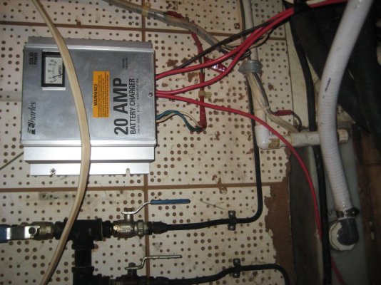
The Charles 20 amp, 2000SP, battery charger has separate outputs: Marine: 2000 SP Series Battery Chargers but apparently it cannot tolerate a failed battery. Yeah, it looks haywired: something to fix; pic.
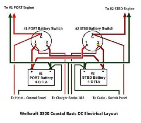
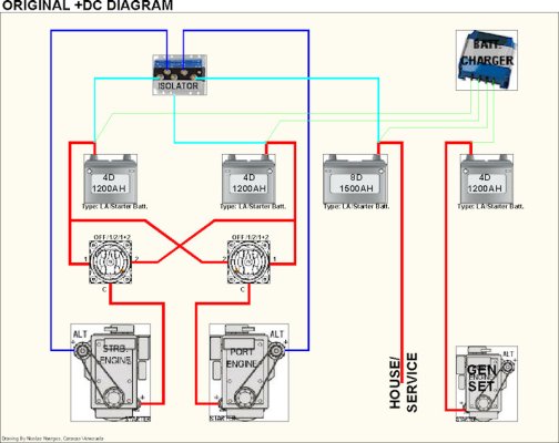
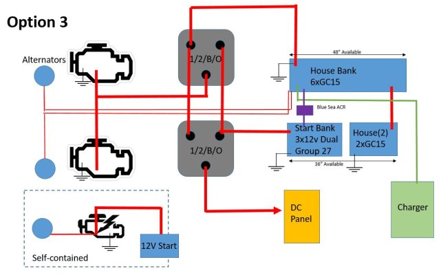
It appears that the Perko diagram below is appropriate for the boat except that it does not show how to interconnect the start bats with the house bank which might be a nice thing to be able to do. I also do not have a stand-alone genset start batt.
I am reasonably certain that I do not have a battery isolator, thus it would seem that the charging circuit interconnections inherent in the engines' alternators would serve to flatten all batts. I presume that the Charles 110v charger isolates the batts.
It would seem that I need to figure out the wiring and interconnections and add a battery isolator. The Guest 2503 at $400 seems to be a reasonable, but expensive choice.
Comments? Enlightenment? Newby here; it should be obvious.
I've got twin Perkins with a group 31 deep cycle battery for each and the lower helm is equipped with battery switches (off, 1, both, 2) that purportedly will enable me to start either engine with either battery. Additionally, I have a house bank (currently 4 6v batteries) and the 12v house panel has a switch for two batteries (off, 1, both, 2).
Nothing seems obvious about how the boat is really wired; I cannot see how the two helm position switches are interconnected and it does not seem to make any difference to whether they start. It also does not seem to have hurt anything(!) by having both switches off; the alternators still work.
Since the boat was pulled last fall, the battery banks went totally flat and the 110v charger refused to charge anything. I've since found that one of the start batteries was probably faulty and was boiling. I disconnected it totally; the charger and the other two banks seem fine.
The Charles 20 amp, 2000SP, battery charger has separate outputs: Marine: 2000 SP Series Battery Chargers but apparently it cannot tolerate a failed battery. Yeah, it looks haywired: something to fix; pic.
It appears that the Perko diagram below is appropriate for the boat except that it does not show how to interconnect the start bats with the house bank which might be a nice thing to be able to do. I also do not have a stand-alone genset start batt.
I am reasonably certain that I do not have a battery isolator, thus it would seem that the charging circuit interconnections inherent in the engines' alternators would serve to flatten all batts. I presume that the Charles 110v charger isolates the batts.
It would seem that I need to figure out the wiring and interconnections and add a battery isolator. The Guest 2503 at $400 seems to be a reasonable, but expensive choice.
Comments? Enlightenment? Newby here; it should be obvious.

")