Battery Cable Butt Connectors

The friendliest place on the web for anyone who enjoys boating.
If you have answers, please help by responding to the unanswered posts.
Boy, I’d feel good with double crimped T&B butts, buried in thick wall adhesive lined heat shrink.
Saying that, I have seen the aftermath of 13kV overhead splice that let go. On a sidewalk, a couple inches deep craters turned to glass. Anyway, the more vibration a joint is subjected to, the more one needs to consider how to mechanically stabilize it. A post will do that, but I submit a good heatshrink job will also.

And something like the Ancor cable tie mounts one on each side of the butt connector to eliminate vibration movement of the butt.
 
Whattayaknow! Right there in Brunswick. I bet you've been in there a few times.

Every transaction I've had with them has been easy, a good price and fast. I also like the quality of their cable.

We had a generator battery issue that we needed a cable quick... Google took the guys to their shop, no sign on building ... They knocked on door and owner let them in and took care of the issue. Guys were flabbergasted at the setup in the warehouse and had a great tour of their operation.Owners were adamant that they didn't encourage walk in biz but were gracious...My engineer was drooling over the setup..
 
Rather than a monster butt connector which seems out of favor, consider placing power posts where the cables currently terminate at the engine room switches. Simply remove the cables from the switches and place them on the power posts. Then run extension cables to the new switch location.
 
@Tom.B #28, @psneeld #29
Note that this is a personal opinion...there is no regulatory prohibition against a properly installed butt splice in the ABYC or ISO Standards or in the CFR.

My concern is that, if the wiring into and out of the butt splice, is not properly secured, then the butt splice will be a under constant tensile force that may, over time, compromise the joint.
Same could be said for ring terminal crimps.


Securing and break in original material on a boat is advised.
 
Rather than a monster butt connector which seems out of favor, consider placing power posts where the cables currently terminate at the engine room switches. Simply remove the cables from the switches and place them on the power posts. Then run extension cables to the new switch location.


Honestly... That sounds... umm... very messy. :blush: But stanger things have happens :)
 
Same could be said for ring terminal crimps.


Securing and break in original material on a boat is advised.


Agreed... proper sizing, implementing, and securing of a butt connector SEEMS like it would be nearly as strong as the cable itself. I will probably order a few, do a couple of test ones, and see how they look. Then go from there.
 
I have some for 4/0 cable but have never used them. No particular reason why not just went ahead and replaced the cable if I needed a longer one.
 
Honestly... That sounds... umm... very messy. :blush: But stanger things have happens :)

Yup, I admit it could be a mess, but each installer and installation is different. Money never being and object to me :), I personally would not use my idea because I would replace the whole run, but maybe, just maybe, the post idea would have some limited appeal over butt connection.
 
@psneeld#26:
Same could be said for ring terminal crimps.

The obvious difference is that the ring terminals will be connected and therefore supported at the power post which is fastened to the vessel structure.
 
@psneeld#26:


The obvious difference is that the ring terminals will be connected and therefore supported at the power post which is fastened to the vessel structure.

But maybe not the cables pulling on the rings.

Seen plenty of bad installs both ways. Both done right are fine.

Just depends on the runs and where they fit best.

One over the other isn't really better, both done right are more than adequate.
 
@psneeld:
I am not going to change your mind, you are not going to change mine. I view it as poor practice and will not use a butt splice on anything >AWG 8.

My opinion. My company. My rules.
 
@psneeld:
I am not going to change your mind, you are not going to change mine. I view it as poor practice and will not use a butt splice on anything >AWG 8.

My opinion. My company. My rules.

Is there any tech data to support this position?
 
I have used butt splices in large/heavy amp load cable in a pinch where not much was at stake. Say in a shop project...or temporary set up..or my tractor. Proper crimps on large butt splices can be difficult even with proper tools and I have seen some overheat when the butt splice joints, or even crimped terminal ends were inadequate. I have even seen this in factory crimped O wire on modern aircraft that carried heavy electrical loads. And these wires were manufactured to strict standards using proper tooling.

Large cable crimping IMO is less than ideal and the success rate of forming a full load carrying connection is less than 100%. If I really need to use a butt splice or make my own cable with large terminal end, it gets crimped and soldered with a torch and then wrapped in THERMAPOD heat shrink tubes. When done it has greater load capacity than the surrounding wire plus the mechanical strength provided by the crimped connector.
 
I once posted a link from either Exide or Trojan battery about the better idea of crimp and solder and the majority of this vocal crowd dismissed it because of ABYC and their mention of solder.
 
My thoughts have been cover already so no need to repeat.
The one addition I will add that I dont think has been made is...
While a butt joint may have fewer failure points than the ring & post alt mentioned it has the benefit of being a clearly visible connection point. The butt on the other hand is much less visible and could be over looked when troubleshooting.
Sort of analogous to a hidden junction in home wiring, a no-no whether wire nuts, crimps and or soldered, but a visible junction/ box is not a problem even if only wire nuts.
 
Yet the troublesome part of ring crimps is also buried within supporting plastic and/or shrink wrap...I see little difference between the two except the rings and powerpost have live connections exposed to the environment typically under a boot or cover.

It would be nice to see some sort of actual research on the subject beyond " thoughts on the subject".
 
Solder or crimp
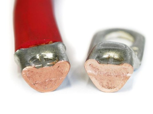
In practice, the difference in resistance between either methods (properly done) is beyond the accuracy range of average multimeters. Hence, the difference is negligible, especially when working on 12v circuits. By that my point is that soldering will not provide “better conductivity”. Once you see the cross-section of a properly crimped cable, where the individual strands can hardly be distinguished, it’s easy to understand why.
Crimped.jpg
A butt connector eliminates one extra connection point at the terminal.
 
If we are going to take the technology to the limit; Burndy Implo fittings win the reliability contest. Tested better than even hydraulic compression fittings.
I rather have an aversion to setting off even small fires in boats, however. Hubbell website.
 
I once posted a link from either Exide or Trojan battery about the better idea of crimp and solder and the majority of this vocal crowd dismissed it because of ABYC and their mention of solder.


Unless someone can show me...the only thing I have seen from ABYC is a statement that the solder can not be the only means of mechanically securing the joint. I agree with you.

Again the main reason is demonstrated above with the picture of what appears to be a perfect crimp. But if you really examine that crimp you will see that the contact area between the crimp and the wire is at the circumference of the inside diameter of the terminal barrel. Does the ampacity of the contact area of the ID of the terminal and the actual wire strands it is touching equal the wire cross section itself? To get around this the barrel of the terminal is lengthened to increase contact area. But the crimp is just a small spot on that barrel. This sometimes results in less than ideal contact area which lowers the load capacity. Then throw in minor issues like contaminates on the wire or ID of barrel that further hinder contact and that connection may be headed for a downward spiral once loaded.
If you take that same crimped terminal and then sweat the solder into the connection...the connection from the ID of terminal to wire runs from the connector all the way to center of wire, not just the outer strands.

FYI...the above is just thinking out load and sharing my own experiences. I am not trying to convince anyone or change what has worked for you. I am sure 99.9% of the time a properly crimped butt or terminal works fine.
 
Does the ampacity of the contact area of the ID of the terminal and the actual wire strands it is touching equal the wire cross section itself? To get around this the barrel of the terminal is lengthened to increase contact area. But the crimp is just a small spot on that barrel. This sometimes results in less than ideal contact area which lowers the load capacity.

Personally, if a crimp doesn't cover the entire length of the connector barrel and I can do it without damaging the first crimp, I'll move the crimper down a little and make another crimp for more surface area. Knock on wood, I've never had a problem with it.
 
Personally, if a crimp doesn't cover the entire length of the connector barrel and I can do it without damaging the first crimp, I'll move the crimper down a little and make another crimp for more surface area. Knock on wood, I've never had a problem with it.

LOL...thats what I do too most of the time. Only when the crimp appears the be critical do I break out the torch.
 
Unless someone can show me...the only thing I have seen from ABYC is a statement that the solder can not be the only means of mechanically securing the joint. I agree with you.

Again the main reason is demonstrated above with the picture of what appears to be a perfect crimp. But if you really examine that crimp you will see that the contact area between the crimp and the wire is at the circumference of the inside diameter of the terminal barrel. Does the ampacity of the contact area of the ID of the terminal and the actual wire strands it is touching equal the wire cross section itself? To get around this the barrel of the terminal is lengthened to increase contact area. But the crimp is just a small spot on that barrel. This sometimes results in less than ideal contact area which lowers the load capacity. Then throw in minor issues like contaminates on the wire or ID of barrel that further hinder contact and that connection may be headed for a downward spiral once loaded.
If you take that same crimped terminal and then sweat the solder into the connection...the connection from the ID of terminal to wire runs from the connector all the way to center of wire, not just the outer strands.

FYI...the above is just thinking out load and sharing my own experiences. I am not trying to convince anyone or change what has worked for you. I am sure 99.9% of the time a properly crimped butt or terminal works fine.
Have to disagree with the bolded.
That proper crimp has the wire tight on all crimp walls and all strands of wire eliminating/reducing heat of a loose connection.
 
Don’t use welding cable. It won’t be tinned.


Welding wire is fine... but we won’t get into that now. That is not the basis of my question. I wanted to know if a proper butt connector had any demonstrative affects on the capacity or safety of a 2/0 DC wire. Regardless of make.
 
Last edited:

Latest posts

Back
Top Bottom