You are using an out of date browser. It may not display this or other websites correctly.
You should upgrade or use an alternative browser.
You should upgrade or use an alternative browser.
Autopilot help...
- Thread starter Steve91T
- Start date
The friendliest place on the web for anyone who enjoys boating.
If you have answers, please help by responding to the unanswered posts.
If you have answers, please help by responding to the unanswered posts.
Comodave
Moderator Emeritus
- Joined
- Jul 2, 2015
- Messages
- 21,283
- Location
- Au Gres, MI
- Vessel Name
- Black Dog
- Vessel Make
- Formula 41PC
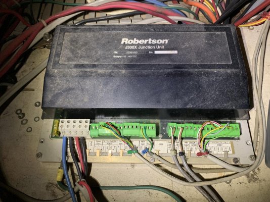
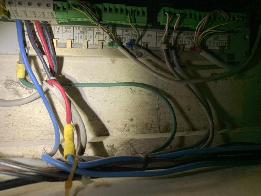
In the second photo, is the red wire going into the connector the same red wire in the duplex wire? The photo shows the red from the duplex going down out of the photo, but does it loop back up into the connector? The red and black going into the connector are most likely the power to the unit. If the red goes into the duplex then I would trace the duplex back to where it comes from and see if there is voltage there.
Comodave
Moderator Emeritus
- Joined
- Jul 2, 2015
- Messages
- 21,283
- Location
- Au Gres, MI
- Vessel Name
- Black Dog
- Vessel Make
- Formula 41PC
Ok, in looking at the better photo, it looks like the power is the red and black on the right of the connector. It looks like they go into a duplex going out to the left. I would trace that duplex and see where it goes, then check voltage there as a start.
tiltrider1
Guru
- Joined
- Aug 2, 2017
- Messages
- 4,344
- Location
- Pacific North West
- Vessel Name
- AZZURRA
- Vessel Make
- Ocean Alexander 54
Your last picture is a Robertson junction box. This is the nerve center of your autopilot. On the far left you have a blue wire. This is 12v +. Next to it is a black wire that should be 12v - . Because your 12v- wire goes directly into a two wire sheath, I suspect it is going to a on/off switch some where. I suspect the black goes to the switch and the red returns. Then red is butspliced into a blue that I suspect goes to a common ground. The red and black wires that look like power/ground are in fact hooked to the solenoid switch. If you traces these wire I suspect they will go to a solenoid switch connected to your hydraulic steering. It looks like you have a constant pressure pump rather than a reversing style.
To diagnose this you can either use a multimeter to test each wire separately or you can follow the black wire until you get to a known common ground.
To diagnose this you can either use a multimeter to test each wire separately or you can follow the black wire until you get to a known common ground.
Last edited:
LarryM
Guru
- Joined
- Aug 5, 2011
- Messages
- 1,069
- Location
- USA
- Vessel Name
- Pelago
- Vessel Make
- Wellcraft 3300 Coastal
OK, looking at your photos, the terminals on the Junction Unit left to right are as follows:
20A Fuse
TB1 - 12v Pos AP Power - Blue
TB2 - 12v Neg AP Power - Black
TB3 - 12v Pump - Red
TB4 - 12v Pump - Black
First, check the fuse. Next, check for 12v across the Blue and Black wire terminals. It looks like the blue might go to an autopilot switch or breaker (just a guess) that will need to be turned on.
If you don't have 12v across TB1 and TB2, there's no need to go any further. Find out why. For troubleshooting, you could temporarily connect TB1 and TB2 to a known good 12v source.
Once you have established power to the Junction Unit, try turning the system on by pressing the STBY/PWR (top left) button on the AP22 control head. That should begin the display of information on the screen.
That should get you started at least.
Do become familiar with the AP22 Owner's Manual in post #20.
Good luck

- Joined
- Aug 29, 2012
- Messages
- 2,679
- Location
- Good Ol' US of A!
- Vessel Name
- Pau Hana
- Vessel Make
- 1989 PT52 Overseas Yachtfisher
To answer one of your original questions- yes, you can use the existing pump should you go to a modern autopilot system.
We had the same system (Robertson AP200DL) and replaces all with the Raymarine Evolution 400 system. Hardest part was pulling the wires- the install itself was easy. Used the existing Capilano pump.
We had the same system (Robertson AP200DL) and replaces all with the Raymarine Evolution 400 system. Hardest part was pulling the wires- the install itself was easy. Used the existing Capilano pump.
Steve91T
Guru
- Joined
- Sep 12, 2016
- Messages
- 898
- Location
- USA
- Vessel Name
- Abeona
- Vessel Make
- Marine Trader 47’ Sundeck
I do have a breaker labeled autopilot, kinda thought that would do it. From the breaker which is right there in the same space as the auto pilot, where would the wires go? Do they go down to the engine room then back up for some reason? I’m new to large boats and how they are wired.
I’m going to try to track down where these wires go to figure out why I’m not getting any power.
One thing about this boat, the PO has the outside painted and then sold it. There are some things that were disconnected for painting and never reconnected.
I’m going to try to track down where these wires go to figure out why I’m not getting any power.
One thing about this boat, the PO has the outside painted and then sold it. There are some things that were disconnected for painting and never reconnected.
tiltrider1
Guru
- Joined
- Aug 2, 2017
- Messages
- 4,344
- Location
- Pacific North West
- Vessel Name
- AZZURRA
- Vessel Make
- Ocean Alexander 54
I don’t have enough information to be sure of what you have. Some one has used poor practices in wiring what I do see. While they used poor practices does not mean anything is wrong. There may be a switch you don’t know about causing all the problems. It’s time for a multimeter and some wire tracing. You can either start at the circuit breaker or start at the junction box.
The ground wire off the junction box looks like a good place to start tracing.
There is no better way to learn about your boat than tracing electrical wires. It’s amazing what you will learn along the way.
The ground wire off the junction box looks like a good place to start tracing.
There is no better way to learn about your boat than tracing electrical wires. It’s amazing what you will learn along the way.
- Joined
- Aug 29, 2012
- Messages
- 2,679
- Location
- Good Ol' US of A!
- Vessel Name
- Pau Hana
- Vessel Make
- 1989 PT52 Overseas Yachtfisher
PH...why the EV400 and not an EV200?
I need to feel....adequate .
Vessel size, good sir- 57', 70k displacement.
- Joined
- Aug 29, 2012
- Messages
- 2,679
- Location
- Good Ol' US of A!
- Vessel Name
- Pau Hana
- Vessel Make
- 1989 PT52 Overseas Yachtfisher
(LOL) Damn good reason! At 42' and about 34K displacement, my EV200 has been fantastic!

Likewise- the EV400 is hands down the best I've used.
Similar threads
- Replies
- 4
- Views
- 432
- Replies
- 9
- Views
- 641
- Replies
- 8
- Views
- 642


