Alternator does not charge

The friendliest place on the web for anyone who enjoys boating.
If you have answers, please help by responding to the unanswered posts.
Maybe I missed this so I shall ask again.
When you measured the output of the alternator, you measured it at the alternator?
There is a fuse in line from the alternator to the battery charger.
If you have good output at the alternator, maybe your inline fuse is 'blown'
Fastest way to check the fuse is, shut the engine down, measure across the alternator fuse with you ohm meter.
You get zero reading across the fuse, reach into your spare parts locker and replace the fuse or install your spare alternator. (innocent look)

Dont even have to take the fuse out to check.
 
Last edited:
I totally agree with you. I wish I had the knowledge of an electrician. Unfortunately, besides basic wirings, it is foggy to me.
I have talked to an electrician already and it is possible that he will do the job for me. I will hire him as my budget allows. I do want my electrical system cleaned up and organized. Some of the existing wiring is very ' home made ' type; others are very professional. The PO spent quite a bit of money on the 50A upgrade and the galvanic isolator installation. So, I have good bases.
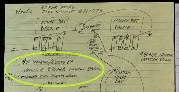
I attach some diagrams, which was done by the electrician, who worked for the PO. It is not perfect, but it can give you enough info on the existing system.

Again, I will not do this alone. If something requires professional knowledge, I will not venture there.

Your opinion is valuable, thank you.


Couple things... opinions are worth exactly what you pay for them..:)
Preface "electrician" with "ABYC marine" for best results. A house or commercial electrician may be knowledgeable and be an expert in their field, but most haven't a clue about 12VDC wiring or the specialized requirements of AC wiring aboard a boat. Let them wire your house or your business, bring them on your boat for fishing or a beer, but don't let them work.Certainly don't PAY them to work. There are exceptions, but the ABYC qualification removes a lot of gray. Best to have an ABYC guy early, it'll cost you less that way than paying them to undo stuff.

See attached pic... Sure about this?? Speaks to the confidence placed in the installer. Just for ease of calculation, a T-105 is 200AH a 6VDC, 8 of them will give you 1600AH @ 6VDC. If they're wired in parallel/series for a 12VDC bank, youll have 800 AH. Half of that is considered usable figuring 50% DOD at max, so you have 400AH of usable power. How long will that power your connected load while at anchor? Do some homework on the solar power sites. The more you learn, the less $$ you'll blow.

Splitting up battery banks adds complexity to wiring, charging, management, and reduces overall capacity (see Peukert's law). A single large bank sized for your demand will retain enough capacity if discharged to 50% DOD to easily start an engine (or two). If you're paranoid about having a dead battery after a night at anchor, keep the genset start battery isolated. See, now you've eliminated the battery isolators, some fuses, two 8D's for the engines, a bunch of wire, and the lovely magic marker instructions on the bulkheads.

Do the math on how many amp hours are consumed in cranking a diesel engine for 5 seconds. Illuminating. Full disclosure: I have a 4D start battery. I was too pig headed to heed Arild Jensen who told me all this years ago. :banghead:
If your cruise plans include time on the hook, solar will be a beneficial inclusion that will enable you to reduce generator run time, and provide a means to regularly float your battery bank. Chronic undercharging is murder on a bank. Literally.

The system. Look at the system.
 

Attachments

  • batts.jpg
    batts.jpg
    78.4 KB · Views: 48
Yes, I know it. I need a good electrician, but they are not cheap. The hourly rates are high and I am a low budget person. I can only do it little by little. $100-150/hr rate adds up really fast.

Just some thoughts / reactions...
If that translates to wanting to DIY at leaast some of the work to save $ I'd recommend a few resources...

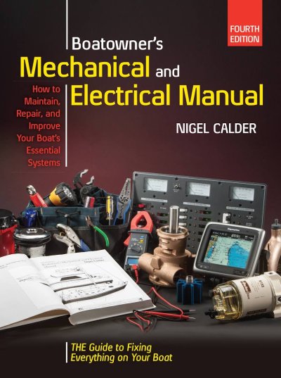
Nigel Calders Book should be helpful to even start to see several different arrangements of batty banks

RC at Compass Marine provides a wealth of knowledge via his MarineHowTo website. I have purchased components from him to help support his education efforts. I have considered using his fee based consulting to advise on redesigning my Mainship factory house / start batty bank but so far haven't taken that step.

I'd start by tracing & sketching what exists now - likely you will learn doing that - then use a pro to check your work and design a system based on your needs and intended use - there's more than one correct way and it will depend on what your use / needs are.
Then decide whether you can do some of the work or need a pro to install it in phases where possible.
 

Attachments

  • Calder - Mech & Elec Manual 4th Ed.jpg
    Calder - Mech & Elec Manual 4th Ed.jpg
    99.6 KB · Views: 38
Couple things... opinions are worth exactly what you pay for them..:)
Preface "electrician" with "ABYC marine" for best results. A house or commercial electrician may be knowledgeable and be an expert in their field, but most haven't a clue about 12VDC wiring or the specialized requirements of AC wiring aboard a boat. Let them wire your house or your business, bring them on your boat for fishing or a beer, but don't let them work.Certainly don't PAY them to work. There are exceptions, but the ABYC qualification removes a lot of gray. Best to have an ABYC guy early, it'll cost you less that way than paying them to undo stuff.

See attached pic... Sure about this?? Speaks to the confidence placed in the installer. Just for ease of calculation, a T-105 is 200AH a 6VDC, 8 of them will give you 1600AH @ 6VDC. If they're wired in parallel/series for a 12VDC bank, youll have 800 AH. Half of that is considered usable figuring 50% DOD at max, so you have 400AH of usable power. How long will that power your connected load while at anchor? Do some homework on the solar power sites. The more you learn, the less $$ you'll blow.

Splitting up battery banks adds complexity to wiring, charging, management, and reduces overall capacity (see Peukert's law). A single large bank sized for your demand will retain enough capacity if discharged to 50% DOD to easily start an engine (or two). If you're paranoid about having a dead battery after a night at anchor, keep the genset start battery isolated. See, now you've eliminated the battery isolators, some fuses, two 8D's for the engines, a bunch of wire, and the lovely magic marker instructions on the bulkheads.

Do the math on how many amp hours are consumed in cranking a diesel engine for 5 seconds. Illuminating. Full disclosure: I have a 4D start battery. I was too pig headed to heed Arild Jensen who told me all this years ago. :banghead:
If your cruise plans include time on the hook, solar will be a beneficial inclusion that will enable you to reduce generator run time, and provide a means to regularly float your battery bank. Chronic undercharging is murder on a bank. Literally.

The system. Look at the system.


Steve I suspect the batteries are L16s which produces the amp/hr capacity in the diagram. The part I don't understand is why to separate the house bank in two banks with a switch. I agree that a marine electrician would help. In reality if the batteries are original they are 9 years old have probably been undercharged and would be the one of the first things to check. From the diagram, I would reconfigure the 2 house banks into one bank. getting rid of the battery switch. Then put an ACR (combiner) between the start and house bank.
 
Maybe I missed this so I shall ask again.
When you measured the output of the alternator, you measured it at the alternator?

I was told that the alternator is purposely not charging the banks. Only the 2 cranks.
My alternator is brand new. I had to replace the old one, because it died.
 
. In reality if the batteries are original they are 9 years old have probably been undercharged and would be the one of the first things to check.


The batteries are 2015.

I like your suggestion of simplifying.
 
Steve I suspect the batteries are L16s which produces the amp/hr capacity in the diagram. The part I don't understand is why to separate the house bank in two banks with a switch. I agree that a marine electrician would help. In reality if the batteries are original they are 9 years old have probably been undercharged and would be the one of the first things to check. From the diagram, I would reconfigure the 2 house banks into one bank. getting rid of the battery switch. Then put an ACR (combiner) between the start and house bank.


I checked again, they ARE L-16's, I zoomed in on one of the photos, and confirmed it. So that makes sense. My mistake, I threw the installer under the bus by not having all the facts and overlooking a detail. That bolsters what others are asserting-and I've alluded to- there's too much that can be missed to attempt to advise the OP. There's a clear need for someone to do a qualified assessment of what he's got before he starts piece-mealing stuff based on advice he receives on the forum. He'll end up with a real mess without a clear plan. Nothing at ALL wrong with getting input and ideas, brainstorming is great! Another post mentioned there's more than one way to do it correctly, but a plan has to ultimately come from one source, otherwise it won't be a plan. Like a project manager, someone has to make sure all those ideas can come together and it all works.

I agree with getting the banks combined. I'd also go a step further & eliminate the start batteries, that's a redundancy that's just a lot of extra stuff to deal with. With that big of a bank, there's just no need for starting batteries. Maybe one GP31 if someone's really paranoid. ACR from house to start batt, alternator with external regulator connected to the house bank with adequate wire size, fused @ 150% of alternator capacity.

This idea of intentionally not connecting the alternator to the house bank is really odd. There had to be some logic behind that, perhaps the PO ALWAYS ran the genset prior to the inverter install and it was never brought up to date??
Have a friend with a 70 Marlow, same deal. Engine alternators did not connect to the batteries- no need, 2 gensets, one fired up before the shore power was dropped. Throwback to pre-inverter mindset, I suppose. It's since been corrected, and he no longer needs to run the genset while underway. Perhaps the same deal here.

All that said, I'll reiterate---Qualified assessment of system-- a PLAN. Only then start changes.
 
Last edited:
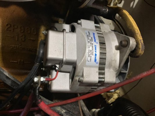
Here is a photo of my new alternator. IMG_0766.jpg
 
"The part I don't understand is why to separate the house bank in two banks with a switch"

In the past it was considered insurance to have 2 house banks , so if one ran flat you did not loose everything.

Today folks would rather have the longer life of using the combined batts (both on switch) as a low voltage alarm is cheap, but batts are not.

Do not ever disconnect an operating alt from the batts as it can blow the diodes in the alt.
 
Steve I suspect the batteries are L16s which produces the amp/hr capacity in the diagram. The part I don't understand is why to separate the house bank in two banks with a switch. I agree that a marine electrician would help. In reality if the batteries are original they are 9 years old have probably been undercharged and would be the one of the first things to check. From the diagram, I would reconfigure the 2 house banks into one bank. getting rid of the battery switch. Then put an ACR (combiner) between the start and house bank.

Okay, so why is having two banks combined with a switch not a good idea? Another responder mentioned Peukart's Law which I guess means some loss in capacity. My boat is wired that way, two banks, with an off-left-right-both switch. The ABYC electrician who rewired my boat chose to do it that way for reasons stated elsewhere, insurance against depleting both banks. Since my 932 amp-hour (total) starts both Lehmans (no starting batteries), I suppose that made some sense but, in fact, when at anchor I always combine the banks cuz I need the full capacity. I would have preferred one bank to make it more simple. So, would there be any significant benefit to rewiring the two banks into one?
 
Looks like it's still internally regulated, it can be modded to use an external regulator, which would give you more charging features.
I don't know about anyone else but I'm pretty good at understanding systems if I can see them, but hopeless at it if someone is just describing it to me.
Everyone seems to have a different opinion on how they want their battery system set up. Buy Calder's book, read it and decide how you want your boat set up then go from there.


Here is a photo of my new alternator. View attachment 86778
 
Okay, so why is having two banks combined with a switch not a good idea? Another responder mentioned Peukart's Law which I guess means some loss in capacity. My boat is wired that way, two banks, with an off-left-right-both switch. The ABYC electrician who rewired my boat chose to do it that way for reasons stated elsewhere, insurance against depleting both banks. Since my 932 amp-hour (total) starts both Lehmans (no starting batteries), I suppose that made some sense but, in fact, when at anchor I always combine the banks cuz I need the full capacity. I would have preferred one bank to make it more simple. So, would there be any significant benefit to rewiring the two banks into one?


The absolute most foolproof system I have seen for boats in our size range is a appropriately sized starting battery or bank. and appropriately sized house bank of similar age and chemistry as the starting batts. Those 2 banks are connected with an ACR or combiner. Doing it this way ensures both banks can be charged by either the alternator, inverter/charger or battery charger and then isolated when ever the charging source is removed.
 
I agree with #10 about the water level rising and causing corrosion. Many boats have an engine ground quite low on the block. A bad enough ground and the alternator might have voltage to itself but no current to the battery. The battery shares the ground with the engine(s). #17 writes a good checkout of the system.
 
Those 2 banks are connected with an ACR or combiner. Doing it this way ensures both banks can be charged by either the alternator, inverter/charger or battery charger and then isolated when ever the charging source is removed.

Can you tell us more about this combiner?
 
I agree with #10 about the water level rising and causing corrosion. Many boats have an engine ground quite low on the block. A bad enough ground and the alternator might have voltage to itself but no current to the battery. The battery shares the ground with the engine(s). #17 writes a good checkout of the system.


The alternator is brand new, only few months old. The previous one was dead, so I replaced with the same brand, but higher amp. 160A.
To my knowledge, the alternator is purposely not charging the banks. Only the starter batteries. Don't ask me why. I don't know.
What I want is this new alternator to charge everything; the banks, the starters.

IMHO, to get it done quickly and correctly, call a tech. He should be able to do it quickly and correctly, without trial and error and below the diodes in the alternator
 
IMHO, to get it done quickly and correctly, call a tech. He should be able to do it quickly and correctly, without trial and error and below the diodes in the alternator

I did. Unfortunately, I have not heard of him, since.
I am talking to another one now.
Regardless, I still want to understand the system.
 
I did. Unfortunately, I have not heard of him, since.
I am talking to another one now.
Regardless, I still want to understand the system.

Of course
 
Okay, so why is having two banks combined with a switch not a good idea? Another responder mentioned Peukart's Law which I guess means some loss in capacity. My boat is wired that way, two banks, with an off-left-right-both switch. The ABYC electrician who rewired my boat chose to do it that way for reasons stated elsewhere, insurance against depleting both banks.


It's not a good idea because Peukert's Law, (over?) simplified, states that rate of discharge affects the total capacity available in a battery. A battery of given capacity will yield more energy if discharged at a lower rate than the same battery will yield at a higher discharge rate- before it is flat or discharged. So 2 battery banks discharged sequentially will take a shorter time to go flat than a single bank of equal capacity.

The "insurance" factor seems to be a throwback to pre-inverter days when usage was configured differently. Loads were more moderate and consistent. It's an archaic concept.
Now, with inverters powering appliances, those loads have changed significantly. Inverters can remove energy at relatively high rates of discharge, so Peukert's Law comes into play predicting how long the battery can deliver that energy before it is depleted, and how long it takes to replace that energy.

So halving a bank and controlling it manually with switches really adds no benefit. On the contrary, it adds complexity, the need to manually monitor and switch, and reduces the overall capacity of the bank while having the potential to consistently increase the DOD for halved banks beyond what that DOD would be for a combined larger bank. two banks sequentially discharged to 50%DOD, combined bank with same energy removed, maybe only 40-45% DOD. Single bank much better for battery longevity.

For battery banks, bigger is better. Most applications have (or should have) battery monitoring instrumentation that makes the likelihood of inadvertently discharging a bank below 50% DOD slim. Another reason for a single bank- easier to monitor, less wiring, more accurate monitoring.
 
Last edited:
It's not a good idea because Peukert's Law, (over?) simplified, states that rate of discharge affects the total capacity available in a battery. A battery of given capacity will yield more energy if discharged at a lower rate than the same battery will yield at a higher discharge rate- before it is flat or discharged. So 2 battery banks discharged sequentially will take a shorter time to go flat than a single bank of equal capacity.

The "insurance" factor seems to be a throwback to pre-inverter days when usage was configured differently. Loads were more moderate and consistent. It's an archaic concept.
Now, with inverters powering appliances, those loads have changed significantly. Inverters can remove energy at relatively high rates of discharge, so Peukert's Law comes into play predicting how long the battery can deliver that energy before it is depleted, and how long it takes to replace that energy.

So halving a bank and controlling it manually with switches really adds no benefit. On the contrary, it adds complexity, the need to manually monitor and switch, and reduces the overall capacity of the bank while having the potential to consistently increase the DOD for halved banks beyond what that DOD would be for a combined larger bank. two banks sequentially discharged to 50%DOD, combined bank with same energy removed, maybe only 40-45% DOD. Single bank much better for battery longevity.

For battery banks, bigger is better. Most applications have (or should have) battery monitoring instrumentation that makes the likelihood of inadvertently discharging a bank below 50% DOD slim. Another reason for a single bank- easier to monitor, less wiring, more accurate monitoring.


Really good explanation :thumb:
 
So long as the generator battery is healthy, you can charge the other batteries enough to start the main engines then you are home free, so to speak.
I have 4x4D batteries. One is only devoted to start the main engine. The 3 others are my house bank.
I have a separate small battery to start the generator. I think everyones' generator has its own, separate start battery, isolated from the house and start battery charging system.
The bow and stern thrusters come off the house batteries.
 
I agree with everything that has been said about the common benefit of having a single larger capacity battery bank instead of two, selectable, smaller capacity battery banks.

The situation in which I disagree is when a single battery bank can meet one's demand, and the second one is purely for redundancy to provide a "switch flip" fix for a failed battery in the primary bank, or for "failed management", e.g. allowing unintended excessive use of a high draw device, of the same.

In these cases, one bank of twice the size could still be (temporarily) disabled by a battery in the bank going bad (it could need to be disconnected, which is likely one wire, but not as easy as a switch). Or, one could benefit from the secondary battery bank in the event of goofed up management resulting in the depletion of the primary.

I suspect most folks would be better served by a single battery bank sized to their needs. But, some folks, for whom weight and/or money are less of a concern might choose to have a redundant bank, whether a twin in capacity (to be alternated for longevity), or smaller (as a backup for only essential loads).

Goals and priorities are so important in optimization.
 
It's not a good idea because Peukert's Law, (over?) simplified, states that rate of discharge affects the total capacity available in a battery. A battery of given capacity will yield more energy if discharged at a lower rate than the same battery will yield at a higher discharge rate- before it is flat or discharged. So 2 battery banks discharged sequentially will take a shorter time to go flat than a single bank of equal capacity.

The "insurance" factor seems to be a throwback to pre-inverter days when usage was configured differently. Loads were more moderate and consistent. It's an archaic concept.
Now, with inverters powering appliances, those loads have changed significantly. Inverters can remove energy at relatively high rates of discharge, so Peukert's Law comes into play predicting how long the battery can deliver that energy before it is depleted, and how long it takes to replace that energy.

So halving a bank and controlling it manually with switches really adds no benefit. On the contrary, it adds complexity, the need to manually monitor and switch, and reduces the overall capacity of the bank while having the potential to consistently increase the DOD for halved banks beyond what that DOD would be for a combined larger bank. two banks sequentially discharged to 50%DOD, combined bank with same energy removed, maybe only 40-45% DOD. Single bank much better for battery longevity.

For battery banks, bigger is better. Most applications have (or should have) battery monitoring instrumentation that makes the likelihood of inadvertently discharging a bank below 50% DOD slim. Another reason for a single bank- easier to monitor, less wiring, more accurate monitoring.

Maerin, thanks so much for the explanation. I do now understand the concept. Next for me, then, is how to rewire everything, as easy as possible, to get one large bank. I never did like the way it was set up.

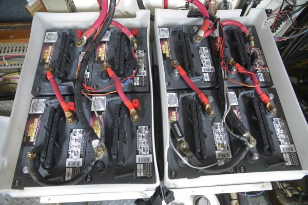
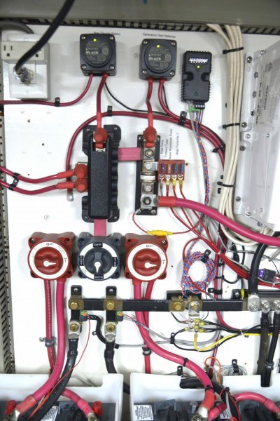
I have attached pictures of the switches and the battery wiring. Note that the two smaller red wires outboard on both the port and starboard switches run to the starters on my two Lehmans. I earnestly welcome suggestions although I am guessing that a lot of work may be required. I am hopeful that the existing switches can be utilized perhaps by not using one of them.
 

Attachments

  • Batteries.jpg
    Batteries.jpg
    156.2 KB · Views: 25
  • Switches.jpg
    Switches.jpg
    146 KB · Views: 30
WHY?

I am still in favor of using a battery to start only.
Two engines, two batteries.

IF you elect to put the two starting batteries on the house bank, get a marine electrical out to do the work. Watch him and ask questions (dont distract him) but, it is better to employ a marine electrician instead of follow the advice from us. LOL
 
A picture may be worth a thousand words, but it falls short of a schematic. It would be difficult to recommend a course of action with only the information derived from a photo. I think you'll find that any ABYC electrician you contact will probably want to get eyeballs on as a first step in any modification. There's just too much subtle but critical detail that can be overlooked. Forums are great for discussing concepts, brainstorming, sharing of what works and doesn't, but can't substitute for an on-site survey by an experienced eye. When it comes to the specifics of how to re-wire your individual system, you're beyond the reach of the forum. Call in a pro. :)


I'm with Old Dan on this call.
 
Back
Top Bottom