AC Generator Ground Question

The friendliest place on the web for anyone who enjoys boating.
If you have answers, please help by responding to the unanswered posts.

Gdavid

Guru
Joined
Jan 4, 2016
Messages
1,382
Location
US
Vessel Name
Graceland
Vessel Make
Mainship 34 MK1
I am connecting the AC wiring for a newly installed generator (new installation, not a replacement) and would appreciate some feedback regarding the ground.

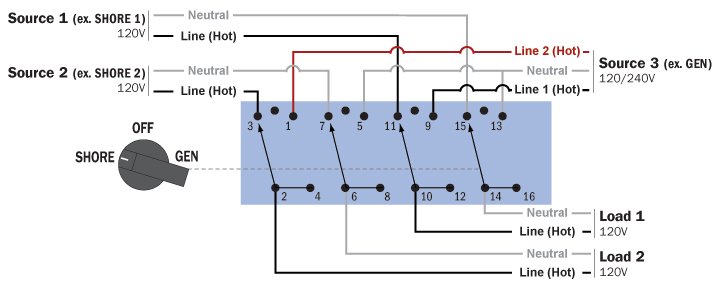
Currently the boat has two 125V 30 amp shore power connections, one feeds the power supply for the air conditioner (nothing else) the other feeds the 125V panel for the boat. I am using a blue seas system switch 6337 that will allow these two circuits to run through the same switch (isolated from each other but controlled by the same lever) or connect to separate legs of the generator 250V so each has 125V. The switch controls the hot and neutral lines for each source and load but does not support grounds. My intention is to tie the grounds from boat loads together with the grounds from the two shore power connection together on one side of a heavy one/off, two post switch (4 wires on a single post) and have the other post connect to a grounding wire leading to the generator), the switch would remain open when on shore power and closed when on generator power to protect from galvanic corrosion and prevent ground fault troubles. An alternate approach would be a galvanic isolator but this seems like an unnecessary item if the AC ground is not bonded to the boat unless away from the dock.
 

Attachments

  • 6337.jpg
    6337.jpg
    63.5 KB · Views: 89
Last edited:
Since all loads on boat are 125v, reconnect gen so both windings are paralleled. No need for them to be in series at 250v and windings then subject to imbalanced load. Wire them in parallel and ground N inside the control box. Reconnect output breaker for windings in parallel at 125v.

Instructions for this are in the gennie operator's manual.
 
Forgetting to close the ground circuit would be dangerous. I wouldn't do it.
 
ALL electric is grounded AT its source.

At the dock side power pole its done somewhere for you.

In an inverter its IN the inverter

With a noisemaker its done AT the noisemaker,

The hard part is switching between the Sources and keeping the ground requirement.

I prefer a plug that is ALL the boat loads and a socket for each source.

This is house sourced stuff , $30 gets everything and there is NO confusion

.And no big buck transfer switch and system.
 
According to ABYC the green grounding conductors for the shore power and the generator must be connected to the engine negative terminal or its bus. There can be no switch in the green grounding wire. The generator output neutral must be grounded at the generator. The generator switch must break both hot and neutral conductors but NOT the green grounding conductor .
 
According to ABYC the green grounding conductors for the shore power and the generator must be connected to the engine negative terminal or its bus. There can be no switch in the green grounding wire. The generator output neutral must be grounded at the generator. The generator switch must break both hot and neutral conductors but NOT the green grounding conductor .

I agree with the above. All AC grounds should be bonded directly to the ground buss and as a side note; don't use the neutral buss for grounds or vise versa as is common in residential panels.
 
Right. ABYC is quite clear that shore power neutrals must only be grounded at the shore distribution panel. They must not be connected to the on board ground bus. The generator neutrals must be connected to the on board ground bus. I was ABYC tech VP for 11 years before going back into boat building.
 
No switches for grounds, all grounds are always positively tied together all the time.

With the gen your breaking hots and neutrals together, so when gen is out of the circuit, the gen's neutral to ground bonding is open circuited by the transfer switch opening the neutral to ground bond, so that is playing nice.

And good idea to switch the gen to 120 VAC only, just jumper the 2 hots and neutrals on the gen side, this way the entire system can share the gen's poles balanced together

I did the same on my own boat, same basic setup. Instead of manual switch I used 2 4PDT power relays to switch the circuits by means of small toggle switches.

I have it set, so that when I plug in shore power, the relay is automatically energized and switch to shore power.

With no incoming power, it is defaulted to gen,
When inverter turns on, it energizes the other relay to switch to inverter power.

these here, but I got the off ebay cheap.
they are rated 35 amps.
https://www.zoro.com/struthers-dunn...MVOcdcSq-UvTSfMTpiKRTRoCYnrw_wcB&gclsrc=aw.ds


I have a safety disconnect relay that if the gen is powered on, breaks the coil power driving the inverter's 4PDT relay, just in case something weird happens. Inverters are delicate devices

I control them though with DC volts about 15 to 16 vdc will activate them.
DC stopped the buzzing, since our marina power is so crappy, big loads on the dock would cause the relays to vibrate and make annoying noise. Alternatively, is get these with 12VDC coils.

the basic schema is this, you can rearrange power in any way you wish.
power_switch_gen.png


inverter, grid, gen are power in sources, ship is power destination.
Using these 4PDT relays, never can any power source interconnect with any other, and all poles are switched.

IF you wanted a fourth AC power source, simply add another power relay, maybe if you had a backup gen? Otherwise can't imagine needing 4 input sources configured.
 
Last edited:
Not the best picture, but here it is, I even welded this box together from an old distribution panel I cut it and welded and made a cover.
Of course this is before all the power wires were hooked into it.

switch1_1.jpg


Been working great for years now. I wanted to go with the 4 pole manual switch, but they wanted $600 and I said no way.
 
Last edited:
Thanks to all for the feedback. I did not find any consensus on generator grounding (in my initial research).

Since all loads on boat are 125v, reconnect gen so both windings are paralleled. No need for them to be in series at 250v and windings then subject to imbalanced load. Wire them in parallel and ground N inside the control box. Reconnect output breaker for windings in parallel at 125v.

Instructions for this are in the gennie operator's manual.


Makes sense. I was thinking that long range a 240 stove may be considered but there is no existing requirement. I did not realize the gen is imbalanced by the series configuration. Easy fix, I will put the jumpers at the generator back to how they were. I used the instructions to set it up for 250v.

I am still not understanding the matter of the generator ground. Specifically, posts 5 and 7 seem to conflict (to me). I understand that the grounding for shore power should only be in the distribution panel on onshore and that is what I am trying to accomplish, but when I am away from the dock I want the ground buss connected to the generator's block but don't see how both can be accomplished without a switch. I would like to clarify that the shore power recepticals are always connected to the ground buss, the switch is just controlling whether the ground buss connects to the generator.
 
Last edited:
I prefer a plug that is ALL the boat loads and a socket for each source.

This is house sourced stuff , $30 gets everything and there is NO confusion

.And no big buck transfer switch and system.

This was considered, but dismissed as a bit cumbersome, but it certainly would have simplified the grounding issue. The big buck switch is easy and right next to the generator's remote panel. The gen manufacturer made a grave warning (posible to break crank shaft) about starting or shutting down with a load on a circuit. Having a convenient transfer switch makes this easy.

As of yesterday, everything is connected and functioning well.
 
sdowney717

I wrote my two last posts before noticing yours. I will read it over again but it is starting to sink in.

Thank you to all and I appreciate no one telling me the stock answer to "hire a professional". In my experience it doesn't always guarantee it being right unless I understand it enough to check the work.
 
sdowney717

I wrote my two last posts before noticing yours. I will read it over again but it is starting to sink in.g

Thank you to all and I appreciate no one telling me the stock answer to "hire a professional". In my experience it doesn't always guarantee it being right unless I understand it enough to check the work.

Oh so true..... :thumb:

And all but a few "hire a pro" posters have moved along thru the years. :D
 
There are three AC conductors. Black (hot) White (grounded neutral) and the Green grounding conductor. The green grounding conductors from any on board AC power source must all be connected at the engine negative terminal or bus. From there the shore power green is run to shore at the shore distribution panel. The shore power white grounded neutral conductor must never be grounded on the boat. It must be grounded at the shore distribution panel. The shore power switch must break both the hot and neutral leads. The grounded neutral of the generator must be grounded and tied to the green grounding conductor on the frame of the generator.The Generator switch must break both the hot and neutral leads. The AC grounded neutral of the inverter must be grounded and connected to the green grounding wire at the frame of the inverter. The inverter switch must break both the hot and neutral leads. According to the National Electrical code and ABYC standards, there can be NO SWITCH in the green grounding conductor! The NEC has only one exception to this and it does permit a galvanic isolator in the green aboard boats.
 
Very clear explanation. I don't understand the op's reluctance to have the gen green ground wire permanently wired to ship's ground as the standards call for.
 
Last edited:
There are three AC conductors. Black (hot) White (grounded neutral) and the Green grounding conductor. The green grounding conductors from any on board AC power source must all be connected at the engine negative terminal or bus. From there the shore power green is run to shore at the shore distribution panel. The shore power white grounded neutral conductor must never be grounded on the boat. It must be grounded at the shore distribution panel. The shore power switch must break both the hot and neutral leads. The grounded neutral of the generator must be grounded and tied to the green grounding conductor on the frame of the generator.The Generator switch must break both the hot and neutral leads. The AC grounded neutral of the inverter must be grounded and connected to the green grounding wire at the frame of the inverter. The inverter switch must break both the hot and neutral leads. According to the National Electrical code and ABYC standards, there can be NO SWITCH in the green grounding conductor! The NEC has only one exception to this and it does permit a galvanic isolator in the green aboard boats.

So the switched connection I ran between the ground buss and the generator is unnecessary ( my greens between the ground buss and each shore power connection never ran through any switch). I do have the generator's neutral grounded at the generator and since it runs does run through the blue sea system switch which makes and breaks both hot and neutral, that is preventing the neutral from being grounded at the boat when on shore power.
 
Correct, a switch in the green grounding conductor is not only unnecessary, it is unsafe. There can be no switch in the green wire per code and standards.
 
"Very clear explanation. I don't understand the op's reluctance to have the gen green ground wire permanently wired to ship's ground as the standards call for."

Ground wires , are connected to neutral wires .

Neutral wired carry some current esp in a 120v setup split from a 240v source (USA) .

The reluctance to induce even minor ac current is to keep down the chance of electrocuting a swimmer , and not add a corrosive load to any underwater metal.
 
I don't see where the inducement of ac current comes in. If the ground lead from the boat to the dock is compromised, then ac faults to ground have no place to go but through the water back to the source. But on the boat, assuming a good shore connection, or away from the dock on generator, the green grounding wire gives a path for faults, rather than have a hot appliance be touched and grounded through a person.
 
In an ideal world, the shore power green grounding conductor would be connected only to shore and would not be connected aboard. But it is far from an ideal world, and in addition to the two ends of the power cord which might have a spot of corrosion and hence resistance, and then the multiple connections and junctions in the dock wiring and resistance in the connection to the ground stake ashore it is very likely that the green wire will have resistance. If there is an on board fault the current it will get to ground through any available path. Therefore we ground the system on the boat too. This protects people aboard from being in the ground path between an on board fault and the engine block and from the engine back to the shore. But it does add increased risk to swimmers around the boat especially in fresh water. This is the subject of the ESD problem we are familiar with. This is a difficult trade off for standards writers to balance. But no one should ever, ever, swim near boats that are plugged into shore power. Especially in fresh water!

It is relatively easy to test to see if you have a ground leak with a clamp on ammeter. Clamp the ammeter around your shore cord with a heavy load on the AC system. The ammeter should read 0 amps. IF it does not read 0, then some current is going to ground through the water. You then de energize all loads and turn them on one at a time to find the problem circuit.
 
Correct, a switch in the green grounding conductor is not only unnecessary, it is unsafe. There can be no switch in the green wire per code and standards.

I think I was not clear. My green between the shore power and the buss is not switched.
 
The reluctance to induce even minor ac current is to keep down the chance of electrocuting a swimmer , and not add a corrosive load to any underwater metal.

Yes this is exactly what I was trying to address, but now I see how grounding the neutral at the generator accomplishes the same thing.

Again thanks to all, I was not trying to be defensive or pigheaded, just wanted to really understand both the how and why.
 
So the main issue is safety regarding shore power. Only remedy is to become self sufficient with on board power sources only. Hopefully the decreased cost and increased efficiency of solar and wind will make the cord obsolete. Does ELCI mitigate the problem of current imbalance in the shore power connection?
 
Yes, the ELCI is there to react to fault current. On older boats, there is more likely to be some small low level leakage. This is causing some heart burn with older boats in newer slips. In some marinas they have a test station where you must report in and test your electrical system before you are assigned a slip.


From ABYC:"11.4.11 Equipment Leakage Circuit Interrupter (ELCI)
a residual current device (RCD) which detects equipment ground fault leakage current and disconnects all ungrounded (110 V & 240 V) and grounded (110 V neutral) current carrying conductors from the supply source at a preset trip threshold."
 
Regarding solar and wind. There is a new and recently patented technology which is not quite ready for market that will make solar panels less expensive and yet epresents a significant emprovement in efficiency. We expect to see this new material commercialized within a year of so.

Regarding wind. Wind power does not generate very much until the wind gets up to about 25. At that point most people are moving to a more protected anchorage. As Nigel Calder says:"Wind is a good option, only after every square inch of your boat is covered with solar panels."
 
Yes, the ELCI is there to react to fault current. On older boats, there is more likely to be some small low level leakage. This is causing some heart burn with older boats in newer slips. In some marinas they have a test station where you must report in and test your electrical system before you are assigned a slip.


From ABYC:"11.4.11 Equipment Leakage Circuit Interrupter (ELCI)
a residual current device (RCD) which detects equipment ground fault leakage current and disconnects all ungrounded (110 V & 240 V) and grounded (110 V neutral) current carrying conductors from the supply source at a preset trip threshold."
not sure if you or I misunderstood Mike66's question...I took it to mean the imbalance on hot legs of a 50 amp cord....ie...2 busses onboard not drawing exactly the same which would be near impossible.....or I wonder if he meant just leakage?
 
Last edited:
I meant just leakage. Trying to comply with standards without killing anyone, especially someone in the water..
Thread drift, I guess.
 
"Very clear explanation. I don't understand the op's reluctance to have the gen green ground wire permanently wired to ship's ground as the standards call for."

Ground wires , are connected to neutral wires .

Neutral wired carry some current esp in a 120v setup split from a 240v source (USA) .

The reluctance to induce even minor ac current is to keep down the chance of electrocuting a swimmer , and not add a corrosive load to any underwater metal.

All the current flowing in on a black wire 120vac must cycle back, return on the white wire. If there is ANY current flowing on the ground safety wire, it would trip a GFCI, so that is not good to have current flowing off the white and black wires.

GFCI and ELCI will sense the difference and turn off the power.

I have a tight AC system, I can run a GFCI on the 30 amp twin inlets, but I dont. Only the microwave and all the outlets are on GFCI.

IMO,FWIW, It is a good idea to have a tight system that does not exceed that 5 milliamp level of current leakage. ELCI is 30 milliamps. I dont have these nuisance trips people talk of on boats when using a GFCI on the shore line.

And the shore power pedestal should be the required location of GFCI or ELCI not on the boat. Is that not how Europe does it?

I have had shore power cords get damaged by whacking, getting pinched accidently, I suppose between boat and dock, and then leak current into the water. An ELCI on the boat wont help that at all. That cord, when I cut it open, had dissolved into the water 6 feet of copper wire, and was hot. A small hole existed in the yellow vinyl cover. Stuff happens that you do not expect..
 
Last edited:
SDowney717, Congratulations on having an electrically tight boat. My testing reveals that most boats are tight, but it the ones that are not that have caused serious problems. ABYC now requires an ELCI on the boat's power inlet for new construction. This will hopefully help. But the NEC now requires it on marina dock feeds.The NEC (National Electrical Code) "NEC 555.3 Ground-Fault Protection. The main over-current protective device that feeds the marina shall have ground fault protection not exceeding 100mA. Groundfault protection of each individual branch or feeder circuit shall be permitted as a suitable alternative."

My comment regarding ELCI was related to these two new requirements. The NEC requirement has caused some great problems at some new marinas. Ocracoke NC had a lot of trouble when the new docks opened a year or so ago. In Ft. Pierce this winter, before you were assigned a slip in the new section of the marina you had to go to a test dock and plug into a test outlet to be sure you had no ac electrical leakage. These are probably just early adopter problems, but the ELCI may actually drive people with older boats to make the necessary repairs and upgrades to prevent AC leakage into the water.

Keeping the electrical system sealed and dry goes a long ways on keeping it tight regarding leakage. And the appliances too need to be in good shape. I thought about that and actually can unplug two branch circuits going to places that can get wet. Just a plug socket in a dry spot, so pull the plug and it disconnects that wire, cheap and easy.
Another way is use a 2 pole switch or just turn off the breaker.

Interesting that 100 milliamp level. What will happen is if 10 boats plug in downstream to that feeder and they had 10 milliamp each of leakage, that tenth boat will trip off power to everyone on that dock. I can see that is not a great solution, but does save the marina the cost of installing individual ELCI devices on every power pedestal.
 

Latest posts

Back
Top Bottom