Seahorse Marine Diesel Duck Vibration - Advice needed

The friendliest place on the web for anyone who enjoys boating.
If you have answers, please help by responding to the unanswered posts.

SeahorseMarineDD54201

Veteran Member
Joined
Jun 4, 2018
Messages
71
Location
China
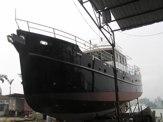
I own a 55’ steel Diesel Duck (DD542) trawler yacht, which is a lengthened version of the very successful 48’ Diesel Duck (DD462) built by Seahorse Marine in Zhuhai, China (Zhuhai is a few hours from Hong Kong). The boat is now registered in Hong Kong since 2014.

DD542 is beautifully built like its DD462 cousin, except it vibrates.

Seahorse knew about the vibration then (unfortunately I did not), but chose to deliver the defective boat. Seahorse also knew the severe financial consequence of either bringing the boat back to the yard (a government policy was and still is in effect that the boat must be towed “$$” and must be bonded at 43% boat value”$$$$”), or fixing the problem by any Hong Kong yards (known for their outrageous charges). Seahorse (Bill Kimley) said the yard is at fault and will fix the problem.

Seahorse has by now tried all simple fixes in sub-contractor yards without success. The boat needs some serious trial and error troubleshooting while sitting in a yard for an extended period.

Bill Kimley and his wife Stella still contend that they are ready to fix the problem. However with all the expenses incurred already, Seahorse refuses to engage another sub-contractor yard. Bill and Stella also will not put in the the cash for bringing the boat back into Seahorse yard, blaming the government for its “crazy rules”. Unreasonable the policy maybe, the policy was known to Seahorse at the time of delivery. It boggles the mind and it is irresponsible of Bill, that he now turns around to blame the government.

Anyway I am now stuck with fixing the boat myself, if I do not want to wait for the government policy to change (I have been waiting for three and half years and there is no talk of new policy changes in this regard). I have very limited financial means, and cannot pay the bond and towage to go back to Seahorse yard. I need to fix the problem in Hong Kong, and I cannot afford any unnecessary trial and error. I hope this post brings me some advices from the community, how to be smart in going about this.

Here are some facts, questions, and plans:

1. Vibration increases with load (none in idle) regardless of forward or reverse. Vibration becomes unmistakably noticeable at 1200rpm and continue to increase with rpm. However at about 1900rpm vibration dampens down RELATIVELY; yet as rpm continue to rise to around 2200rpm (engine max out at 2500rpm), vibration not only is pronounced, it goes through cycles of peak and trough every few seconds, as if something is flexing then bouncing back.

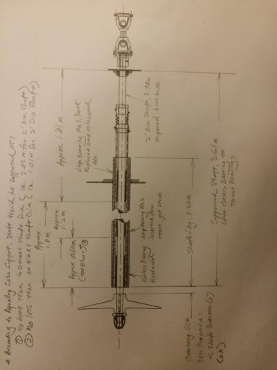
2. Compared with the very successful DD462, DD542 has a longer shaft at 4 meters (about 31cm longer than DD462), at the same diameter of 2”. Seahorse (Bill Kimley) is adamant the shaft is not too thin (engine power is 178hp), and this claim seems to agree with calculations by reputable shaft suppliers.

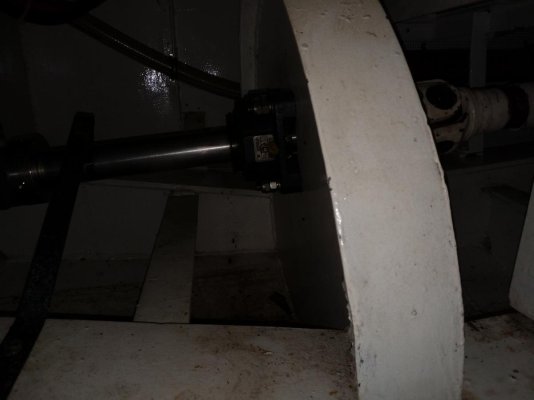
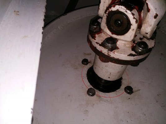
3. However there is a concern where to place the whip bearing for such a long shaft, between the shaft exit Cutlass bearing, and the (forward) thrust bearing. Seahorse experimented with the location and has relocated to the presently just about at the middle of the shaft, about 1.8 meter from either the Cutlass bearing or the (forward) thrust bearing. So the shaft is on one end supported by a Thrust Bearing, the other end by the shaft exit Cutlass Bearing, and in the middle by a whip bearing. This should conform to the guideline of 40xdiameter (of shaft) which is 2 meters. But there is no improvement on vibration.

4. At this point engine, engine mount (anti-vibration), engine alignment, propeller type, propeller size, propeller clearance (cavitation), shaft straightness (checked when pulled out), whip bearing location have all been checked and tried. The latest attempt was to check if the 3 blade Max prop (feathering), new to Seahorse Diesel Ducks, was the cause. A smaller fixed 4 blade prop with more hull clearance, and generated maximum only 50+% power, was installed. If there is no vibration the plan was to then go for a 100% sized fixed 4 blade prop. The vibration became less, BUT STILL VERY evident despite the reduced loading. Incidentally Seahorse (Bill’s wife Stella) actually took this as an improvement. It boggles the mind again …

5. I contacted the late George Buehler who is the father of the wonderful Diesel Duck design. George told me about earlier Seahorse Diesel Ducks, and suggested me to buy a new name brand shaft. Based on what he saw with an earlier 55’ Diesel Duck built by Seahorse, the Chinese made shaft “could not hold shape”. The earlier 55’ had such a bad vibration that the coupling came off. The problem was completely fixed by the owner after delivery, by changing out the shaft and re-aligning the drive train.

6. Seahorse (Bill Kimley) disagreed with George on shaft material as an issue, despite known shaft quality problems with the earlier DD55 (and a couple of DD462s according to George). But I am willing to give it a try. Though the Chinese made shafts are shown to be adequate for DD462, but being longer they may not be enough for the lengthened DD542. The "cycling of vibration with peak and trough" mentioned in Point 1 suggests the shaft is flexing under load. Such a job would take a day or so in a Hong Kong yard if well planned. I can pay that expense and demand repayment from Seahorse.

7. I plan to install a proper name brand shaft and re-install the original 100% Max Prop. I ask for advices from the community, if anything else obvious I should account for with my limited financial means.


Thank you all in advance.


The owner of Seahorse Marine Diesel Duck DD542
 
Last edited:
You need a proper vibration analysis. Based on what you posted, you don't really know what is causing the vibration. Is it in sync with shaft rotation, blade passing frequency, engine firing pulses, or some combination or some harmonic? The beat frequency you mentioned indicates more than one source.

Where is the vibration present?

Go into more detail about the vibration as there are some good technical people here.

Replacing a 4m long 50mm dia shaft is not a trivial expense. I would not go that route until it is known to be the cause.

Describe it well. If it is the shaft you should see displacement of the visible part of the shaft.

Post pics of engine mounts and shaft line from inside.
 
Putting on my Mechanical Engineer Hat the above post is spot on a tech skilled in vibration analysis with proper equipment should be able to pin point with almost 100% certainty what component is the culprit. These guys factor in tons of variables such as the various rotation speeds of different components and how they interact with each other. This over the last 20 years has really became an exact science and not alot of unknown are left over if you have right man on the job. Harmonic Issues typically are alot easier to fix than they are to isolate without a vib analysis.
 
So unfortunate, such a condition in an otherwise fine vessel. In almost any combination of machinery and surrounding structure, somewhere in the spectrum of dimentional possibilities, the combinations seem to cooperate for harmonic ring. Sometimes one can get lucky and by simply by welding an appendage to the structure, the need for a stubborn vibration to express itself can be satisfied there instead of the rest of the structure. The was no mention of other potentially dampening elements in the boat like comparing the vibration with full or empty tankage. If it were my boat (like you, with limited funds), before I spent any money I’d probably be using sand-bags, mud or water bladders in the engine room area to see what, if any improvement could be affected. Next, I would add some shaft zinks and grind them to see if I could make the same vibration worse. I’d want to check the engine flywheel visually for wobble. While underway, I’d want to check each motor and trans mount with a broomstick to ear. What I did next would depend on those findings, but it would likely be some sort of separation of several contributing elements. An Aquadrive, for example, would put the prop thrust into a cross member instead of transmission or engine mounts. Yes, there’s a lot to do. Best of luck and please keep us informed. Any of us could have this problem next week.
 
Best of luck, and very sorry for the problems with an otherwise great boat. For what it is worth, Delfin is also 55', her shaft is around 8 feet long, the longest unsupported run is 4 feet, and is 2 1/2" in diameter. The gear is 3.8:1, so at our normal cruising rpm of 1400, her 44" wheel is turning pretty slowly. Just using that as a comparison, a 2" shaft of that length seems a bit noodle like, at least to me. Is Monel stiffer than 316 stainless and if so, is that an option?
 
Thanks to the first 3 replies suggesting a vibration test/analysis by a professional, and some self help tricks. Some members of other boating forums also suggested a professional test, and apparently these days the results are quite definitive and not even expensive.

After we got nowhere in March 2017 replacing the Max prop with a fixed 4 blade, and with the yard neither willing to engaged another sub-contract yard, nor willing to bring the boat back into Seahorse, I suggested they send an engineer down to Hong Kong (a couple of hours by the fast catamaran ferry) to help me as a layman, with some sea trials and vibration observation.

This would have been a step in the right direction at essentially no cost.
Also the yard environment being on a shallow and busy river, is really no comparison with an empty typhoon shelter in Hong Kong. Bill and Stella refused and no explanation was offered.

I will talk to Bill Kimley and Stella Zheng again about a professional vibration test/analysis, and hope they have some sense that Seahorse funding this really should save everyone money and time.


I will upload some information as suggested by Ski in NC, and hope to get additional comments. Need some time to gather the information.
 
Last edited:
Best of luck, and very sorry for the problems with an otherwise great boat. For what it is worth, Delfin is also 55', her shaft is around 8 feet long, the longest unsupported run is 4 feet, and is 2 1/2" in diameter. The gear is 3.8:1, so at our normal cruising rpm of 1400, her 44" wheel is turning pretty slowly. Just using that as a comparison, a 2" shaft of that length seems a bit noodle like, at least to me. Is Monel stiffer than 316 stainless and if so, is that an option?

Thanks for the information. I need such real reference cases as yours, otherwise everything is possible. So a bit more clarification requested:

a. What is your engine power ? Mine is 178HP, and my gear box is 3:1.
b. Do you have a thrust bearing ? If so do you consider thrust bearing as "support" against radial forces (thrust bearing seems to me to be used for aixal forces).
 
Last edited:
Thanks for the information. I need such real reference cases as yours, otherwise everything is possible. So a bit more clarification requested:

a. What is your engine power ? Mine is 178HP, and my gear box is 3:1.
b. Do you have a thrust bearing ? If so do you consider thrust bearing as "support" against radial forces (thrust bearing seems to me to be used for aixal forces).

She is powered with a 270 hp CAT 3306, but we rarely use more than 80 hp when cruising, so I would consider our respective power demands very similar. I have no thrust bearing. The shaft is coupled to a Twin disc MG509 gear, travels back approximately 4 feet unsupported to the forward cutlass bearing, then another 4 feet to the aft bearing. When replacing the cutlass bearings 4 years ago, I had the shaft trued, as it was a few mics out of being perfectly straight. There is no vibration, other than some harmonics that are endemic to that CAT at certain rpms. The engine is soft mounted with Sounddown mounts. I sprayed anti-vibration compound over all internal surfaces before overlaying the interior with 1/4" acoustical cork.

Good advice on the professional survey for the source of the vibration.
 
Last edited:
Take a good look at the rudder too, I had a vibration which I cured by moving the anodes that were mounted in the middle of the rudder to the bottom and by later welding a 3" angle to the trailing edge. Make sure the rudder mounts are solid and there is no play in the linkage. I also had to replace the connecting gudgeon pin with a new later model with a grease fitting. This is a wild guess as your boat is pretty new.

Is there any vibration in neutral? Is the engine operating normally?

My shaft is 2.5" for 250 hp and is only about 2 meters long with a 36" wheel. Perhaps with a thicker shaft you could eliminate the support bearing?
 
I think Buehler's suggestion to replace the shaft with one of known quality is a good one. Without material analysis of your existing shaft you can't really be sure it's adequate. The fact that they had a problem previously is telling. 2" diameter sounds small. The other thing you could try, if it's cheaper, is 2 intermediate bearings so you end up with less than 40x unsupported. Without knowing the alloy and strength of your shaft there is no reason to assume that 40x is sufficient. The other thing I'd look at, just so I understood it and could eliminate it, is the thrust bearing. In your list of things done you don't mention checking the alignment of the thrust bearing. It's taking all the shaft load it's alignment is critical.
 
I have seen transmissions exhibit similar symptoms and mask the source. Thousands spent before FINALLY isolated. Just a thought. This was in aF37 Great Harbor with Yanmars. Doubt it is your issue but worth mentioning.
 
Oh, one other thing. In two similar cases where driveshaft “whip” was suspected to be the source of vibration, one shaft was replaced and the problem was rectified. The other was not replaced, but a mercury fluid balance ring (I believe it was only one ring) was installed on the 2” shaft at various locations until the vibration was eliminated in the regular operating RPM range of the shaft. It seems to me that the whip was noticeable at max RPM, but the device delayed the imbalance (and therefore delayed the whip) for an additional 500 RPM, which was all that was necessary to meet the performance expectations of the owner. Sorry for the lack of detail here, but I’m working with the memory of two old engineers. The mercury fluid balance ring was about $100 from this outfit:

DRIVESHAFTS
 
I think Buehler's suggestion to replace the shaft with one of known quality is a good one. Without material analysis of your existing shaft you can't really be sure it's adequate. The fact that they had a problem previously is telling. 2" diameter sounds small. The other thing you could try, if it's cheaper, is 2 intermediate bearings so you end up with less than 40x unsupported. Without knowing the alloy and strength of your shaft there is no reason to assume that 40x is sufficient. The other thing I'd look at, just so I understood it and could eliminate it, is the thrust bearing. In your list of things done you don't mention checking the alignment of the thrust bearing. It's taking all the shaft load it's alignment is critical.


Thanks for the suggestion. Additional whip bearings were indeed thought of by Bill Kimley and myself.

Presently there is one whip bearing sitting right in the middle of the Prop end Cutlass Bearing and the Transmission end Thrust Bearing. So far I deliberately left out why there is a Thrust Bearing: The shaft is not directly coupled to the transmission (in that case I believe the Transmission will manage the axial load). Instead a Single Caden Shaft connects the shaft to the transmission. I know Single Caden Shaft is tricky to install, and need to be re-inspected again (along with engine mount, thrust bearing, dripless bellow, propeller, rudder). Therefore I did not mention this before to avoid too much discussion. However Seahorse did re-check the alignment of the shaft, Caden Shaft, and Transmission.

Having said the above, I always wonder whether half of the shaft, between the whip bearing and the Thrust Bearing, is actually supported against deflection. Thrust Bearing in my mind supports axial load, not radial load. So I was thinking the whip bearing should be located at the end of the stern tube at the transmission side (as in all DD462s), and a second whip bearing placed right in the middle of the stern tube.

But there are also concerns that now with 3 bearings in the stern tube (and a Thrust Bearing), they cannot unambiguously define a straight shaft line.

One additional undisclosed information: Without moving the current whip bearing, the Hong Kong Sub-Contractor actually tried to insert another whip bearing from the prop end. The bearing got stuck after moving 2 ft. Seahorse decided at last minute against my request, and told its staff NOT TO GO TO HONG KONG and monitor Sub-Contractor work (that boggles the mind too). They were not on site to explain why the bearing got stuck, and offered a guess the stern tube MAY have mud.

I am very suspicious of this guess. The boat was driven only once lasting a few hours from another earlier sub-contractor yard visit where Seahorse staff took out the shaft. They must have ensured the stern tube was clean .... Anyway vibration existed before the additional bearing inserted, and did not improve afterwards.

With all the above said, can someone tell me to what extent does a Thrust Bearing support HALF of the shaft from deflection ?
 
Last edited:
Oh, one other thing. In two similar cases where driveshaft “whip” was suspected to be the source of vibration, one shaft was replaced and the problem was rectified. The other was not replaced, but a mercury fluid balance ring (I believe it was only one ring) was installed on the 2” shaft at various locations until the vibration was eliminated in the regular operating RPM range of the shaft. It seems to me that the whip was noticeable at max RPM, but the device delayed the imbalance (and therefore delayed the whip) for an additional 500 RPM, which was all that was necessary to meet the performance expectations of the owner. Sorry for the lack of detail here, but I’m working with the memory of two old engineers. The mercury fluid balance ring was about $100 from this outfit:

DRIVESHAFTS


Very interesting device which I am not aware of.

As stated in another reply, I wonder if Thrust Bearing can support nearly HALF of the entire shaft from deflection. The shaft near the Thrust Bearing is the only exposed and short section (something like 1 or 2 ft, the rest is inaccessible in the stern tube), and may be the place to put this mercury device. I wonder if it balances against any deflection, or it could introduce another force that the Chinese shaft needs to bear with. So a brand name shaft would give a peace of mind for me.
 
The thrust bearing devices I've seen, Aquadrive etc support the shaft radially and axially. Not sure what yours looks like. Also can't visualize your carden shaft. I'm assuming your prop shaft ends with a flange attached to the thrust bearing which is rigidly and strongly attached to the hull, there needs to be a means of adjustment for alignment. You could then have a shaft with carden joints at both ends from the front of your thrust plate to the engine. This would allow you to soft mount the engine. Also keep in mind that carden joints don't like running at 0 degrees of angle.
Since your stern tube ends fairly close to your trans where did they put the intermediate bearing? Did they just put another cutless in the stern tube? If so did they check alignment. Putting more than one bearing in the stern tube assumes that the tube is exactly straight and that it and the shaft have the same centerline. I doubt if either is the case.
 
Can I ask for clarification of one point? You say a "SINGLE CARDAN SHAFT" do you mean a shaft with one universal joint or one on each end?

The problem with U joints is that they need to operate in pairs, or you will get all sorts of chatter since you're making one end speed up or slow down, assuming your engine is turning a constant speed (totally unrealistic, we know). The larger the angle of the U joint, the more pronounced the chatter or vibration will be.

The Yokes of the U Joints have to be matching on each end, or you'll get a lot of vibration on the drive end. By this I mean that the yokes on the drive and driven ends should be parallel, same as the central drive line should be. If you're out of phase by a few degrees, it will cause all sorts of vibrations.

We swapped out a Pickup truck with a 5 cylinder Deutz engine as a test. The guys took it to the drag strip, after opening up the governor on the engine just to see what it would do. They revved up the engine to 3200 or so and dropped the clutch and it took off, but had a very bad vibration. The torque of the engine and 300 lb flywheel twisted the yoke of one end about 20 degrees out of alignment. It still ran but shook like a paint shaker.

This might be it...
 
Look what I found on the Internet! Apparently, some smart Aussies have figured out the single ended true constant velocity joint problem.

https://www.thompsoncouplings.com/

If you have one cardan joint and are willing to replace it with one of their couplings it may solve the problem of the engine turning at a fairly constant speed and the Cardan joint changing the speed twice with every revolution.

How did we get to 16 messages on this topic without a SINGLE image??

An image speaks a thousand words, and a model speaks a thousand images...
 
There are at least ten issues that can potentially cause the vibration the OP is experiencing. A listing of each of these by a suitable yard experienced in design, construction and repairs is required. Then start with eliminating the easiest items first, some of which are cited on this thread already. One area not mentioned is hull construction itself leading to distortion as power applied.

Fingers crossed and parts swapping can lead to despair. Be methodical, thorough and analytical in building the list and eliminating potential culprits. There may be more than one. Question, how close to the Cheoy Lee yard is the vessel?
 
Look what I found on the Internet! Apparently, some smart Aussies have figured out the single ended true constant velocity joint problem.

https://www.thompsoncouplings.com/

If you have one cardan joint and are willing to replace it with one of their couplings it may solve the problem of the engine turning at a fairly constant speed and the Cardan joint changing the speed twice with every revolution.

How did we get to 16 messages on this topic without a SINGLE image??

An image speaks a thousand words, and a model speaks a thousand images...

Those videos are fantastic. What a great device!
 
The thrust bearing devices I've seen, Aquadrive etc support the shaft radially and axially. Not sure what yours looks like. Also can't visualize your carden shaft. I'm assuming your prop shaft ends with a flange attached to the thrust bearing which is rigidly and strongly attached to the hull, there needs to be a means of adjustment for alignment. You could then have a shaft with carden joints at both ends from the front of your thrust plate to the engine. This would allow you to soft mount the engine. Also keep in mind that carden joints don't like running at 0 degrees of angle.
Since your stern tube ends fairly close to your trans where did they put the intermediate bearing? Did they just put another cutless in the stern tube? If so did they check alignment. Putting more than one bearing in the stern tube assumes that the tube is exactly straight and that it and the shaft have the same centerline. I doubt if either is the case.

open


open


Thank you for making me aware of radial/axial thrust bearing.

Based on the marking (photo attached) on my thrust bearing and the parts list of a DD462 (mine does not have the detail), my thrust bearing is an Emerson Morse SFA-RFB-112C-1 3/4". I cannot find this part number from Googling yet to understand how it works. Will keep trying.

The attached pictures help to answer your questions:

1. The thrust bearing is mounted on a purpose built thick reinforced mounting plate (the big white wall between the thrust bearing and the Caden Shaft.

2. Near the end but not at the end, the Prop Shaft passes through the Thrust Bearing.

3. At the end of the Prop Shaft is a custom flange, that connects the Prop Shaft to the Caden Shaft.

4. By "Intermediate" Bearing I assume you mean the water lubricated whip bearing (the shaft was designed with only three bearings, the Cutlass Bearing and Prop End, the Thrust Bearing at the Caden Shaft/Transmission End, and the Whip Bearing right in the middle, though another Whip Bearing was inserted for trouble shooting purpose later). The "Intermediate" whip bearing is inside the stern tube about 1.8m from the Thrust Bearing.

5. The Shaft, Thrust Bearing, Cutlass Bearing, Whip Bearing are all standard Seahorse practice proven in the DD462s. The only difference from DD462 is the the longer length, requiring moving the Whip Bearing (DD462 has it right at the entrance of the stern tube). Though all these need to be re-checked, they are likely to be ok (except Whip Bearing location/qty). Seahorse is also aware of the trickiness of Caden Shaft (>3 deg offset and <.5 deg mis-alignment).

6. The engine and prop were run with the boat out of water (bearings lubrication maintained), and the prop rotated smoothly. The shaft was pulled and checked to be straight. Therefore I think the centerline is ok. Of course under load it may be a different story.


Thanks again for the tips and suggestions !
 

Attachments

  • Thrust Bearing.jpg
    Thrust Bearing.jpg
    71 KB · Views: 188
  • 20180610_132417.jpg
    20180610_132417.jpg
    60.2 KB · Views: 198
There are at least ten issues that can potentially cause the vibration the OP is experiencing. A listing of each of these by a suitable yard experienced in design, construction and repairs is required. Then start with eliminating the easiest items first, some of which are cited on this thread already. One area not mentioned is hull construction itself leading to distortion as power applied.

Fingers crossed and parts swapping can lead to despair. Be methodical, thorough and analytical in building the list and eliminating potential culprits. There may be more than one. Question, how close to the Cheoy Lee yard is the vessel?


Thank you for the comments. Bill Kimley suspected "panting" of the hull. However Geroge Buehler disagreed that "there is nothing there to pant". I am trying to get Bill to fund a vibration test/analysis so we don't all have to guess.

Seahrose yard has relocated and if memory serves me correct, the two yards are probably 20 minutes apart by driving. Cheoy Lee is not an option either. Indeed if there is a way to bring the boat in without draining the yard's cash, Bill and Stella still contend they would fix the vibration problem.
 
Last edited by a moderator:
Can I ask for clarification of one point? You say a "SINGLE CARDAN SHAFT" do you mean a shaft with one universal joint or one on each end?

The problem with U joints is that they need to operate in pairs, or you will get all sorts of chatter since you're making one end speed up or slow down, assuming your engine is turning a constant speed (totally unrealistic, we know). The larger the angle of the U joint, the more pronounced the chatter or vibration will be.

The Yokes of the U Joints have to be matching on each end, or you'll get a lot of vibration on the drive end. By this I mean that the yokes on the drive and driven ends should be parallel, same as the central drive line should be. If you're out of phase by a few degrees, it will cause all sorts of vibrations.

We swapped out a Pickup truck with a 5 cylinder Deutz engine as a test. The guys took it to the drag strip, after opening up the governor on the engine just to see what it would do. They revved up the engine to 3200 or so and dropped the clutch and it took off, but had a very bad vibration. The torque of the engine and 300 lb flywheel twisted the yoke of one end about 20 degrees out of alignment. It still ran but shook like a paint shaker.

This might be it...

Thank you for your comments. Indeed the Single Caden Shaft has one U-Joint at each end. However it has been checked and is unlikely the problem (trying to get Bill Kimley to fund a vibration analysis though).

Single Caden Shaft is a standard configuration and practice for all Seahorse Diesel Ducks. I consider Seahorse to be very experienced in installing. Seahorse is aware of the tricks such as "in-phase", mis-alignment < 0.5 deg, offset > 3 deg, etc. Whatever Seahorse' practice (some may frawn on), it is proven in the way that all their other Diesel Ducks do not vibrate (except the earlier ones mentioned by George Buehler, and probably all corrected by owners by now). Seahorse also re-checked the alignment.

The only thing different is my Caden Shaft is longer than those on DD462s, and I wonder if that might be a contributing factor. The Caden Shaft body are two cylinders, one inserted into the other, so the length is adjustable. I do not see any fastening device to fix the length, so I suspect the two cylinders float with respect to each other, and the combined length is dynamically adjustable. As a layman I am not that comfortable with this arrangement (if my observation is correct).

Incidentally the two Caden Shaft cylinders are inserted into, and angularly locked to each other via teeth, similar to the teeth on a gear. Since the two halves need to be in phase, I just can't understand why the use continual teeth, as they give possibility the two halves may have a whole range of angular offset.
 
Look what I found on the Internet! Apparently, some smart Aussies have figured out the single ended true constant velocity joint problem.

https://www.thompsoncouplings.com/

If you have one cardan joint and are willing to replace it with one of their couplings it may solve the problem of the engine turning at a fairly constant speed and the Cardan joint changing the speed twice with every revolution.

How did we get to 16 messages on this topic without a SINGLE image??

An image speaks a thousand words, and a model speaks a thousand images...


My apology. A few pictures attached for now. Still digging up more detailed information in response to the first 3 replies to this thread.
 

Attachments

  • 542 modifiled General Arrangement1-2012-03-03.pdf
    697.6 KB · Views: 70
  • Shaft.jpg
    Shaft.jpg
    64 KB · Views: 152
  • 20180610_123558.jpg
    20180610_123558.jpg
    84.9 KB · Views: 120
  • P1010007.jpg
    P1010007.jpg
    99.2 KB · Views: 123
Wow, 3.26m shaft log with a cutless and two whip bearings... Better not have it run dry!

I'm glad there are two joints on the cardan shaft, so that's not the issue. Is there any deflection of the telescoping cardan shaft under load (with the original prop)? Does it require a telescoping shaft? Is there that much movement of the engine on its mounts?
 
The two joints in the Cardan shaft must have the same angle to the shaft. Also the two joints must be phased correctly, this is very easy to get wrong. You have a sliding spline joint between them, which allows assembly with the two joints in any orientation limited only by the number of splines. The drawing does show correct phasing, your pictures do not show both joints. Are they correctly phased?

The mercury ring balancer can correctly out of balance, but is unlikely to correct whip, since the amount of whip will vary with rpm.
 
So your thrust bearing is just a flange bearing bolted to a plate. Weird in that flange bearings aren't usually even rated for axial load only radial but this one is intended to take axial loading. Certainly a bare bones solution, it's about a $100 bearing. By the numbering you can figure that they've turned the shaft down to 1-3/4" at the bearing. That way the thrust is taken by the shoulder of the turned down shaft hitting the bearing. How do you align that thrust bearing? The bearing itself will adjust to the plate being out of square to the shaft but something needs to be adjustable for centerline.
The carden shaft is just standard with a joint at each end, you need the splined slip joint to take up any length changes that might occur. The engine moving on it's mounts is could cause a length change. Only problem with this style shaft is that you can get some chattering from the splined slip joint. It is critical that the 2 carden joints are in phase, you can't just put the 2 pieces together any old way.
It appears in your drawing that there are 2 bearings in the shaft tube. How do you know the tube is straight? Doesn't do any good to check the shaft for straight on the bench and then put it in a tube that you don't know is straight.
Have to say that Seahorse did about the bare minimum in materials and engineering with this set up.
Really no way you're going to resolve this on the internet. You need someone who knows what they're doing at the boat. This stuff isn't complicated you just need to understand what you're doing and work through the steps.
 
Have you checked that the flanges at each end of the carden shaft are absolutely parallel and have no run-out?
 
I'm hardly an expert, but it seems to me that the intermediate cutlass (whip bearing as you call it) is compensating for a shaft that's too small. And as pointed out, if the shaft tube isn't perfectly straight, then that intermediate bearing could be off center and actually contributing to the problem rather than reducing it.


I suspect the "correct" fix is to step up the shaft diameter such that it can be supported with only the thrust bearing and the prop-end cutlass, yet have the strength to still run true. Now this is only practical if the stern tube is large enough.


I agree with the professional vibration analysis, and it may be worth your own money to fund it. But I think it will be hard to do with nearly all of the shaft enclosed in the stern tube. Ideally you would put a dial gauge on the shaft to measure runout at various shaft RPMs, but I doubt that would be possible given the construction. I would discuss this with any prospective "pro" proposing a vibration analysis to get a sense of what they can actually check given the construction.
 
Wow, 3.26m shaft log with a cutless and two whip bearings... Better not have it run dry!

I'm glad there are two joints on the cardan shaft, so that's not the issue. Is there any deflection of the telescoping cardan shaft under load (with the original prop)? Does it require a telescoping shaft? Is there that much movement of the engine on its mounts?

If I understand you correctly, I mentioned this concern as well that the Caden shaft being extended, can also deflect.

But how to measure the deflection if any ? the surface of the Caden shaft is rough so I cannot use a depth gauge nor a laser.
 
The two joints in the Cardan shaft must have the same angle to the shaft. Also the two joints must be phased correctly, this is very easy to get wrong. You have a sliding spline joint between them, which allows assembly with the two joints in any orientation limited only by the number of splines. The drawing does show correct phasing, your pictures do not show both joints. Are they correctly phased?

The mercury ring balancer can correctly out of balance, but is unlikely to correct whip, since the amount of whip will vary with rpm.

Yes, the Caden Shafts are correctly phased.
 
Back
Top Bottom